


TABLE OF FIGURES
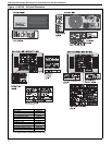
Figure 1: UHA 30 - 45 Label Placement ...................................2
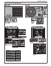
Figure 2: UHA 60 - 75 Label Placement ...................................3
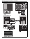
Figure 3: UHA 100 - 125 Label Placement................................4
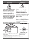
Figure 4: Installation Clearances and Clearances
to Combustibles..........................................................7
Figure 5: Suspension Methods ............................................... 11
Figure 6: Shelf-Mounting Methods.......................................... 11
Figure 7: Wall Shelf Mounting and Hanging Suspension........ 12
Figure 8: Vertical Louvers (Optional)....................................... 13
Figure 9: Vent and Roof Detail................................................ 17
Figure 10: Standard Vented Heater - Vertical
and Horizontal Vent Termination ............................17
Figure 11: Standard Vented Heater - Common
Vertical Vent Termination........................................ 18
Figure 12: Separated Combustion Heater - Vertical
and Horizontal Vent Termination ............................19
Figure 13: Concentric Vent Box............................................... 19
Figure 14: Concentric Vertical and Horizontal Vent
Termination - Separated Combustion Heater .........20
Figure 15: Gas Connection .....................................................22
Figure 16: Automatic Burner Control Sequence......................30
Figure 17: Gas Valve for Models UHA[X][S] 30 - 45................30
Figure 18: Gas Valve for Models UHA[X][S] 60 - 125..............31
Figure 19: Manual Reset Limit Switch.....................................33
Figure 20: LED Diagnostic Codes...........................................34