


SECTION 9: WIRING
23
SECTION 9: WIRING
All heater models require constant 120 V/1Ø/ 60 Hz
power supply. Check heater rating plate for electrical
rating for proper circuit sizing. For servicing, a
disconnect switch of proper electrical rating should
be installed in the vicinity of the heater.
All heaters are equipped with thermostat
connections suitable to power a 24 V thermostat.
Heater must be wired and electrically grounded in
accordance with local codes. In the absence of local
codes in accordance with: United States: refer to
National Electrical Code
®
NFPA 70 - latest revision;
Canada: refer to Canadian Electrical Code CSA
C22.1 Part I - latest revision.
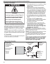
9.1 Positioning Thermostats
A room thermostat should be mounted on a
vibration-free wall or column at a height of
approximately 5' (1.5 m) from the floor to measure
the ambient temperature. It should be clear of both
cold drafts and the direct path of warm air from the
heater.
Avoid mounting thermostat on outside walls or in
areas directly exposed to radiant heat or sunlight.
Install wall tag in a visible location near thermostat
See Page 5, Section 2.1 for wall tag details.
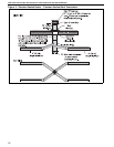
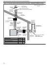
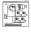
9.1.1 Fan Control
The heater’s axial fan can be used during the off-
season for air circulation. A low-voltage
programmable thermostat with a fan switch (P/N
90425400) must be See Page 23, Section 9.2.
used. For thermostat connection details. For the use
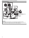
of multiple heaters on one thermostat, See Page 24,
Section 9.3 through Page 25, Section 9.4
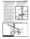
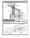
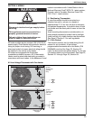
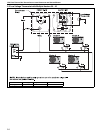
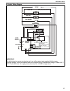
9.2 Low Voltage Thermostat with One Heater
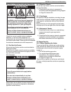
WARNING
Electrical Shock Hazard
Disconnect electrical and gas supply before
servicing.
This appliance must be connected to a
properly grounded electrical source.
Failure to follow these instructions can
result in death or electrical shock.
Electrical
Supply
Terminal
Strip
R
G
W
C
R
W
Electrical
Supply
R
G
W
C
R
G
Terminal
Strip
24 Volt
Thermostat
Heating
Only
24 Volt
Thermostat
with Fan
Control
W
C
Gas
Supply
Gas
Supply