


UHA LOW PROFILE UNIT HEATER INSTALLATION OPERATION AND SERVICE MANUAL
10
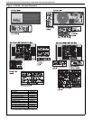
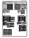
SECTION 5: MAJOR COMPONENTS
5.1 General
Heaters are designed for installation above 6'
(1.8 m). These heaters must be installed within the
heated space. Duct delivery systems are not
permitted with axial fan units. When handling or
supporting the heater from below, ensure that the
weight is taken at the support points.
The gas or electrical supply lines must not be used
to support the heater.
Do not locate the gas or electrical supply lines
directly over the path of the flue products from the
heater.
The heater must be installed in accordance with
clearances to combustibles as indicated on the wall
tag and this manual.
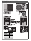
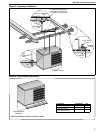
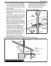
5.2 Shelf Mounting and Suspension
Four suspension points (3/8" nuts) are located on
the top of the heater. Drop rods must be 3/8"
diameter mild steel.
When handling or supporting the heater from below,
ensure that the weight is taken at the support points.
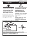
For typical suspension, See Page 11, Figure 5.
For typical shelf mounting on existing shelf, See
Page 11, Figure 6
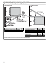
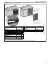
5.3 Wall Mounting
For typical suspension, See Page 12, Figure 7. Wall
mounted heaters blowing parallel to the wall can
only be installed with the service door away from the
wall.
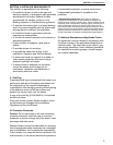
The wall mounting brackets must be attached to a
suitable wall using all mounting holes. Screw sizes
less than 3/8" may not be used. In order for the wall
mounting brackets to adequately carry the weight of
the heater, it must be installed according to best
building practices.
WARNING
Crush Hazard
Use 3/8" threaded rod
minimum.
Failure to follow these
instructions can result in
death, injury or property
damage.