


SECTION 9: WIRING
27
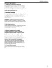
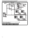
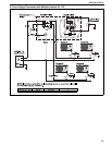
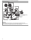
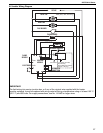
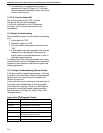
9.6 Ladder Wiring Diagram
FLAME
SENSOR
PRESSURE SWITCH
THERMOSTAT
CONNECTION
6
3
4
5
2
1
120 VAC
TRANSFORMER
FLUE BLOWER
AXIAL FAN
AXIAL FAN
UHA (300, 350, 400 Only)
GAS
VALVE
ELECTRODE
IGNITION
MODULE
Flame
Spark
Limit Switch
Limit Switch (UHA 300,
350, 400 Only)
Manual Reset Limit Switch
(UHA 30 - 125 Only)
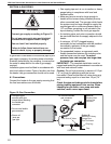
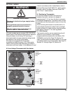
IMPORTANT:
For field wiring into service junction box, or if any of the original wire supplied with the heater
must be replaced, it must be replaced with wiring material having a temperature rating of at least 105° C
(221° F) and 600 volts. For supply connections, use No. 14 AWG or larger wires.