


3
WARNING: Make sure the unit is disconnected from the power source before
assembling, disassembling or adjusting any components.
WARNING: The cutting edges on the chain are very sharp so always wear protective
gloves when handling it.
WARNING: Always unplug the Chain saw from the power source before adjusting the
chain tension.
This unit requires assembly.
UNPACKING
• Carefully remove the product and any accessories from the box.
• Inspect the product carefully to make sure no breakage or damage occurred during shipping.
• Do not discard the packing material until you have carefully inspected and satisfactorily operated
the product.
POLE SAW ASSEMBLY
The Remington Telescoping Pole Saw consists of a chain saw attached to a telescoping pole
assembly with the following items:
• Handle Bracket (1)
• Knob (1)
• .250” Lock Washer (1)
If any parts are damaged or missing, please call 1-866-206-2707 (U.S.) or 1-877-696-5533 (Canada)
for assistance.
Before operating either the Chain Saw or the Pole Saw, make certain that you read and understand
ASSEMBLY INSTRUCTIONS
KNOW YOUR UNIT
APPLICATIONS
This unit may be used for the purposes listed below:
• Cutting small limbs.
• General tree pruning.
all important safety information. Your Remington Telescoping Pole Saw is designed as a dual purpose
product. This means that when it is not attached to the Telescoping Pole Assembly, the electric Chain
Saw can be used for pruning jobs near ground level. However, If you want to trim or prune taller
trees the Chain Saw must be securely attached to the Telescoping Pole Assembly. Here is a safe and
simple assembly process to follow:
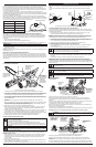
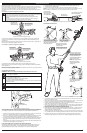
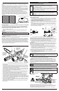
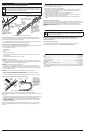
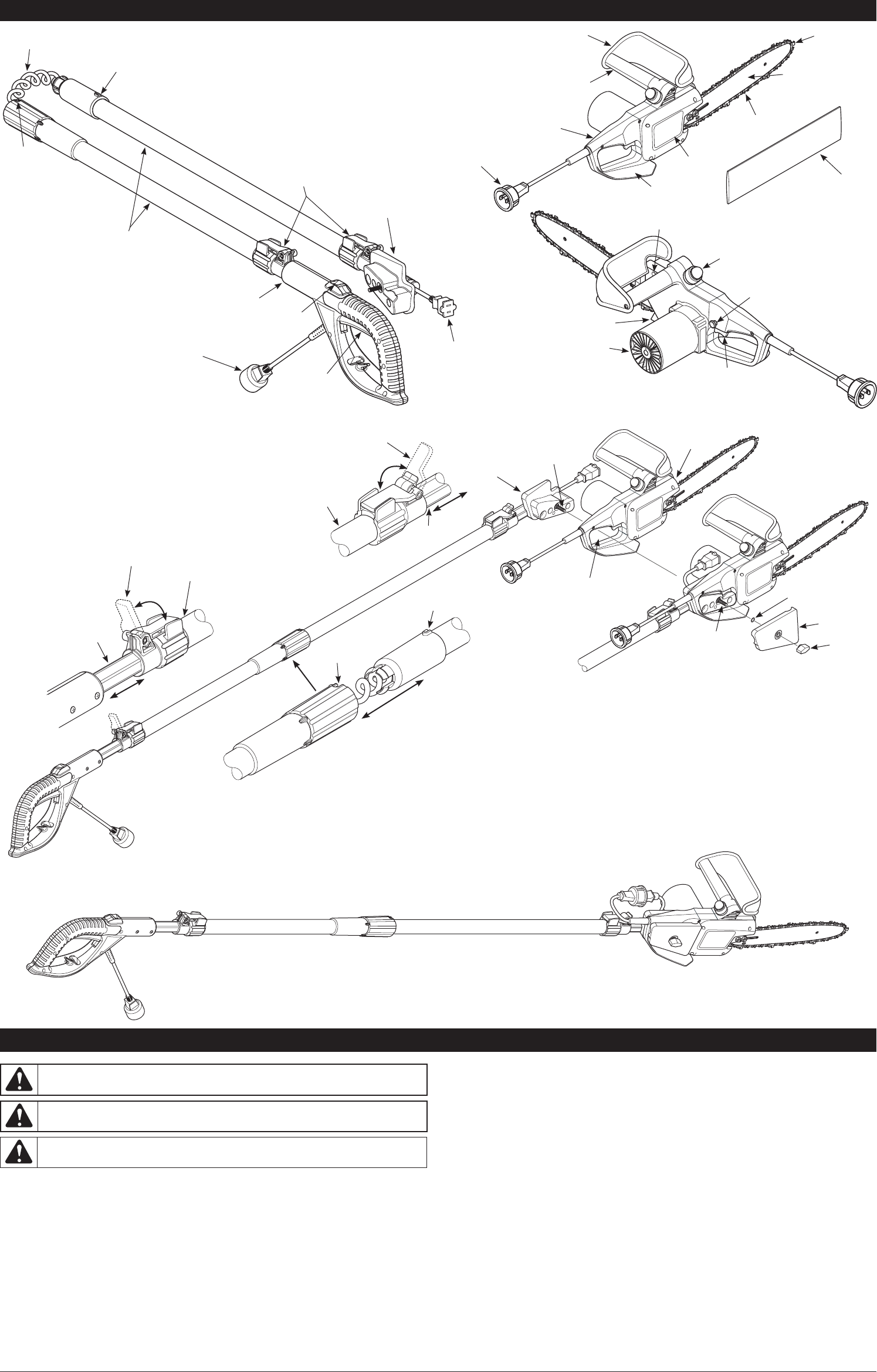
1. Unfold the Telescoping Pole Assembly so that it lays flat as shown (Fig. 4A).
NOTE: DO NOT connect the pole saw to the power supply until it has been completely assembled.
2. Align both ends of the Telescoping Pole Assembly so that the Locking Notch can be inserted into
the Locking Groove (Fig. 4B). The Pole Assembly is designed to be permanently fixed and can not
to be disassembled later on.
3. Push firmly so that the Locking Notch sits fully inside the Locking Groove.
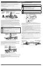
4. Set the Chain Saw flat on a table alongside the Pole Bracket.
5. Align the Pole Bracket inside the Rear Handle of the Chain Saw as shown. (Fig. 4B)
6. Gently press the Pole Bracket into this gap while holding the Trigger Lockout Switch. Make sure
that the Pole Bracket sits securely beneath the Trigger. This is to make sure the Trigger is set to
the “On” position when everything else is fully assembled.
7. Slide the Handle Bracket on to the Clamping Bolt as shown. (Fig. 4B)
8. Thread the Lock Washer and Knob onto the Clamping Bolt.
9. Turn and tighten the Knob one or two times to make full contact with the Handle Bracket. This
fully secures the Telescoping Pole Assembly to the Chain Saw.
10. Insert Chain Saw Power Cord into the Pole Receptacle as shown. (Fig. 5)
SAFETY FEATURES
LOW KICKBACK SAW CHAIN helps significantly reduce kickback or the intensity of kickback, due to
its specially designed depth gauges and guard links.
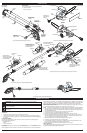
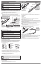
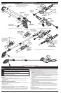
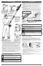
Fig. 2 Remington RM1015SPS Telescoping Pole Assembly
Outer Pole
Trigger
Lockout
Electric Power
Cord (Internal)
Clamping Levers
(to adjust length
of Pole)
Locking
Notch
Locking
Groove
Electric Power
Receptacle
(connects to
Chainsaw)
Electric Power Cord
(connects to
Extension Cord)
Pole Bracket
(attaches Pole to
Chainsaw)
Trigger
Handle
Sprocket
Cover
Guide Bar Nose
Guide Bar
Saw Chain
Scabbard
Front Hand Guard
Rear Hand
Guard
Rear
Handle
Electric Power
Plug (connects
to Pole)
Front Handle
Oil Level
Sight Hole
Oil Cap/Squeeze Bulb
Spike
Trigger Lockout
Switch
Trigger
Switch
Motor Housing
Fig. 3 Remington RM1015SPS Chainsaw (Right and Left Sides)
Push firmly to ensure the
Locking Notch sits fully
inside the Locking Groove
Locking
Notch
To adjust length of
Outer Pole - loosen Cam
Levered Collet and slide
Inner Pole forward
Inner
Pole
Handle
Bracket
Locking
Groove
Outer Pole
Pole Bracket holds Trigger
in the “ON” position
Clamping Bolt
Rear Handle
Chainsaw
Cam Levered
Collet
To adjust length of
Outer Pole - loosen Cam
Levered Collet and slide
Inner Pole forward
Inner
Pole
Outer Pole
Lock Washer
Clamping
Bolt
Knob
Tighten Knob 1 1/2 to 2 turns
after it makes contact with
Handle Bracket
Pole Bracket
Cam Levered
Collet
Fig. 4A Assembly Instructions for Remington RM1015SPS Pole Saw
Fig. 5 Assembled View of Remington RM1015SPS Pole Saw
Fig. 4B Assembly Instructions for connecting Telescoping Pole Assembly to Chain Saw