


English---8
545218616 Rev. 1 12/15/08
DESCRIPTION
Safety equipment
The following equipment on the blower is
designed for protecting personnel and
materials. These components should
receive special attention whenever you
operate, inspect and service the blower .
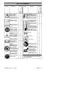
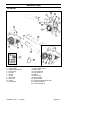
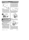
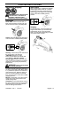
Stop switch
S The stop switch (A) is used to stop the
engine.
Muffler
S The muffler is designed to give the low-
est possible noise level and to direct the
engine’s exhaust fumes away from the
operator . Muf flers fitted with catalytic
converters are also designed to reduce
harmful exhaust components.
S The engine exhaust fumes are hot and
can contain sparks, which may cause
fire if they come in contact with dry or
flammable material.
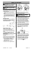
S Some blower models, especially those
sold in countries where the climate is
dry, are equipped with a spark arresting
screen (B). This screen must be cleaned
or replaced at specific intervals. See the
Maintenance section.
A
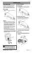
W ARNING: The muffler is ex-
tremely hot while the engine is run-
ning and after it has stopped. DO
NOTTOUCHTHEMUFFLERIFITIS
HOT! This can cause severe burns.
B
O
t
h
er equ
i
pment
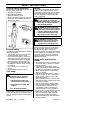
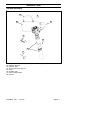
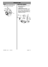
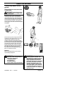
Throttle trigger
S The speed and the output of the engine
are regulated by the throttle trigger (C).
Variable speed control
S The variable speed control (D) is de-
signed to allow setting engine speed as
necessary during blower use only.
S To avoid causing damage to the unit, DO
NOT attempt to use the variable speed
control during starting or during vacuum
use.
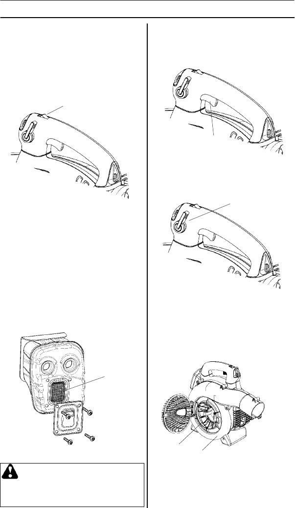
Fan housing
S The blower fan housing (E) and the fan
impeller (F) provide high performance air
discharge.
C
E
F
D