


9
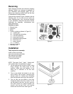
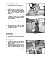
4. Place a level upon the machine table, and
adjust the screws over the foot pads as
necessary. When the machine is level,
tighten all four hex nuts against the
machine’s base.
Unpainted surfaces, such as the work table and
fence, have been given a protective coating at
the factory. This should be removed with a soft
rag moistened with a good commercial solvent.
Do not use acetone, lacquer thinner, gasoline or
any flammable solvents. Do not use an abrasive
pad.
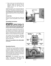
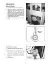
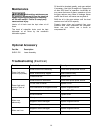
Control Box
Swing out the control box (Figure 4). Use the set
screws to control the tightness of the mounting
arm.
Grounding Instructions
Electrical connections must
be made by a qualified electrician in
compliance with state and local codes. The
machine must be properly grounded to help
prevent electrical shock and possible death.
A power plug is not provided with the SLR12.
You may either connect one, or "hard-wire" the
saw directly to your electrical panel provided
there is a disconnect near the machine for the
operator. Consult electrical schematic on pages
30 and 31 for further clarification of wiring setup.
This machine must be grounded. Grounding
provides a path of least resistance to help divert
current away from the operator in case of
electrical malfunction.
Make sure the voltage of your power supply
matches the specifications on the motor plate of
the machine.
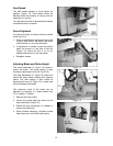
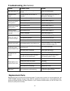
Operating Controls
The buttons on the control panel are explained
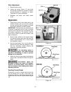
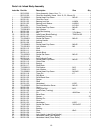
in Figure 5. After making electrical connections,
the machine should be turned on to verify the
direction of rotation. The blade arbor should
rotate counterclockwise when viewed from front
of machine (Figure 6). If rotation is wrong, turn
off the machine, disconnect power and switch
any two of the three electrical leads.
IMPORTANT: The emergency stop button
(Figure 5) shuts down all operations on the
machine simultaneously. To release the
emergency stop button, twist it clockwise.
Figure 4
Figure 5
Figure 6