


5
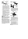
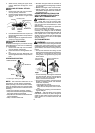
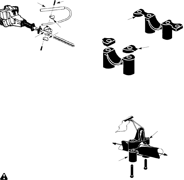
Screw
Mounting
Bracket
Handlebar
Bracket Cover
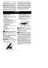
1. Place the mounting bracket over the up-
per shaft above t he arrow on the safety
label. Be sure to use the correct mount-
ing bracket for either the 1″ (2.5 cm) or
7/8″ (2.2 cm) diameter upper shaft.
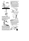
2. Position one of the bracket covers under
the upper shaft and align the m ounting
bracket and the bracket cover screw
holes. Insert two screws into the screw
holes.
3. Secure the mounting bracket by tighten-
ing the screws with the hex w rench.
4. Locate the decal on the handlebar. This
decal includes an ar row. Position th e
handlebar with the mounting bracket at
the end of the arrow.
5. Position the second bracket cover over
the handlebar. Align themountingbrack-
et and the bracket cover screw holes.
Again make sure the handlebar is at the
end of the arrow .
6. Insert two screws and hand tighten only.
Be sure the handlebar is installed cor-
rectly; then, tighten each screw securely
with the hex wrench.
SHOULDER STRAP ASSEMBLY
WARNING: Proper shoulder strap
and handlebar adjustments must be made
with theengine completelystoppedbeforeus-
ing unit. T he shoulder strap clamp must be
installed a s shown above the handlebar o n the
upper shaft ( powerhead end of un it).
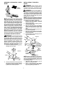
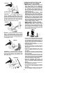
NOTE: The lower shoulder strap clamp has
twospacertabsattached. Thesetabs arepro-
vided to adapt this attachment for use with
powerheads that have a 1″ (2.5 cm)diameter
upper shaft (the shoulder strap clamp will not
tightendownsecurelyon the1″(2.5cm)diam-
eter upper shaft without using these spacer
tabs). Thetabs mustbebrokenoffcompletely
before u se and placed over the screw holes
onthe lowershoulderstrapclamp.Thesetabs
are not needed for powerheads with a 7/8″
(2.2 cm) upper shaft.
Spacer Tabs
LOWER SHOULDER STRAP
CLAMP
Spacer Tabs
positioned for use
on 1″ (2.5 cm)
diameter
upper shaft
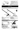
1. Place the upper shoulder strap clamp
overtheuppershaftabovethehandlebar .
2. Position the lower shoulder strap clamp
under theupper shaft andalign theupper
andlowerclampscrewholes (usespacer
tabs between upper and lower clamps if
necessarytosecureclamp, i.e.for 1″(2.5
cm) diameter upper shaft).
Upper Shoulder
Strap Clamp
Screws
Lower Shoulder
Strap Clamp
POWERHEAD
END
ATTACHMENT
END
3. Insert two screws into the screw holes.
4. Secure shoulder strap clamp by tighten-
ing screws with the hex wrench.
5. Insert your right arm and head through
the shoulder strap and allow it to rest on
your left shoulder . Make sure the danger
sign isonyourback andthehook istothe
right side of your waist.
NOTE:A one-halftwist isbuiltintheshoulder
straptoallow thestrapto restflatontheshoul-
der.
6. Adjust the strap, allowing the hook to be
about 6 inches below the waist.
7. Fasten the strap hook t o the clamp and lift
the tool t o the operating position.
8. Try on shoulder strap and adjust for fit
and balance beforestarting the engineor
beginning a cutting operation.
NOTE: It may be necessary to r elocate the
shoulder strap clamp on the shaft for proper
balancing of unit.