


4
S Store unit so the blade cannot accidentally
cause injury.
S Store unit indoors, out of reach of children.
If situations occur which are not covered in this
manual, use care and good judgment. If you
need assistance, call 1--800--554--6723.
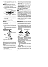
SPECIALNOTICE:Exposureto vibrations
through prolonged use of gasoline powered
hand tools could cause blood vessel or nerve
damage in the fingers, hands, and joints of
peoplepronetocirculationdisorders o rabnor-
mal swellings. Prolonged use in cold weather
has be en linked to blood vessel damage in
otherwise healthy people. If symptoms occur
such as numbness, pain, loss of strength,
change in skin color or texture, or loss of f eel-
ing inthe fingers, hands, or joints,discontinue
theuseof thistooland seekmedicalattention.
An anti-vibration system does not guarantee
the avoidance of these problems. Users who
operatepower toolsonacontinualandregular
basis must monitor closely their physical
condition and the condition of this tool.
SAVE THESE INSTRUCTIONS
ASSEMBLY
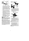
CARTON CONTENTS
Check carton contents for the following:
S Brushcutter attachment
S Handlebar
S Handlebar mounting bracket for 1″ shaft
S Handlebar mounting bracket for 7/8″ shaft
S Bracket cover (2)
S Shoulder strap
S Upper shoulder strap clamp
S Lower shoulder strap clamp(with spacer tabs)
S Handlebar bracket screws (4)
S Shoulder strap clamp screws (2)
S 4--point weed blade (assembled o n brush-
cutter attachment)
S Large nut for installing blade
S Retaining washer
S Cupped washer
S Metal shield (assembled on brushcutter at-
tachment)
S T rimmer head
S Plastic shield
S Wing nut (screwed onto plastic shield)
S Attachment hanger
S Hex wrench
WARNING: If received assembled, re-
peat all steps to ensure your unit is properly as-
sembled and all f asteners ar e secure.
Examine parts for damage. Do not use dam-
aged parts.
NOTE:If you need assistance or find thatparts
are missing or damaged, call 1-800-554-6723.
TOOLS REQUIRED
S Hex wrench (provided)
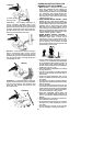
INSTALLING BRUSHCUTTER
ATTACH MENT
CAUTION:
When removing or installing at-
tachments, place the unit on a flat surface for
stability.
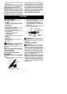
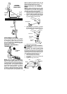
1. Loosen the coupler by turning the knob
counterclockwise.
Coupler
Knob
LOOSEN
TIGHTEN
2. Remove the shaft cap fromthe brushcut-
ter attachment (if present).
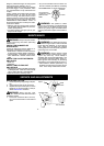
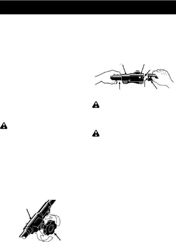
3. Position locking/release button o fattach-
ment into guide recess of coupler.
4. Push theattachment intothecoupleruntil
the locking/release button snaps into the
primary hole.
5. Before usingtheunit, tightentheknobse-
curely by turning clockwise.
Coupler Primary Hole
Upper
Shaft
Locking/
Release
Button
Lower
Attachment
Guide Recess
WARNING: Make sure thelocking/re-
lease button is locked in the primary hole and
the knob is securely tightened before operat-
ing the unit.
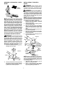
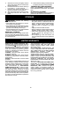
HANDLEBAR ASSEMBLY
DANGER:RISKOFCUT. Toavoidse-
rious injur y, the barrier portion of the handle-
bar must be installed as shown on the upper
shaft ofthepowerheadtoprovidea barrierbe-
tweenoperatorandthespinningblade. Attach
handlebar mounting bracket above arrow o n
safety warning decal onthe upper shaft(pow-
erheadend ofunit). Ensure handlebaris posi-
tioned on mounting bracket at t he end of the
arrow on the handlebar decal.
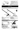
NOTE: T wo mounting brackets are included
with this attachment. Both brackets are provided
to adapt this attachment for use with power-
heads that have either a 1″ (2.5 cm) diameter or
a7/8″ (2.2 cm) diameter upper shaft. The cor-
rect bracket must be used to ensure that the
handlebar is m ounted securely to the upper
shaft b efore use.