


8
ASSEMBLY
WARNING:
If received assembled,
repeat all steps to ensure your unit is properly
assembled and all fasteners are secure.
Examine parts for damage. Do not use dam-
aged parts.
NOTE:
If you need assistance or find parts
missing or damaged, call 1-800-554-6723.
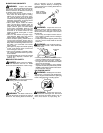
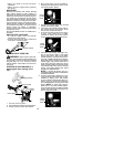
It is norm al for the fuel filter to rattle in the
empty fuel tank.
Finding fuel or oil residue on muffler is normal
due to carburetor adjustments and testing
done by the manufacturer.
TOOLS REQUIRED
S
Hex wrench (provided)
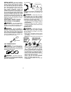
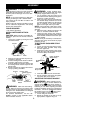
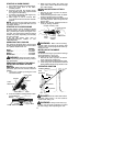
INSTALLING PRUNER ATTACH-
MENT
CAUTION:
When removing or installing at-
tachments, place the unit on a flat surface for
stability.
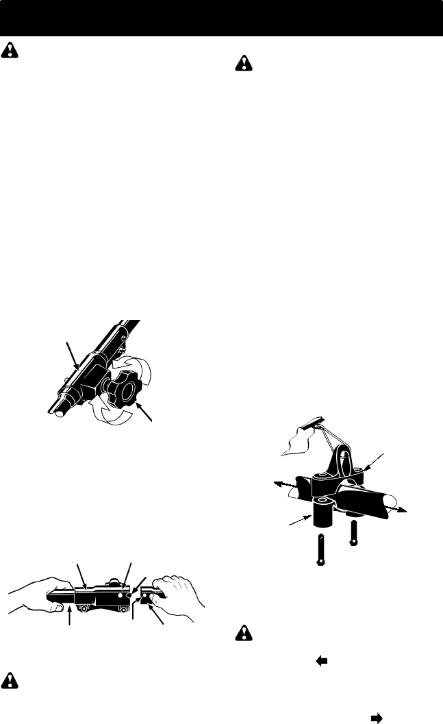
1. Loosen the coupler by turning the knob
counterclockwise.
Coupler
Knob
LOOSEN
TIGHTEN
2. Remove the tube cap from the pruner at-
tachment (if present).
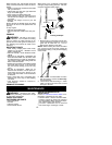
3. Position locking/release button of attach-
ment into guide recess of coupler.
4. Push the attachment into the coupler until
the locking/release button snaps into the
primary hole.
5. Before using the unit, tighten the knob se-
curely by turning clockwise.
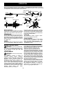
Coupler Primary Hole
Upper
Tube
Locking/
Release
Button
Lower
Attachment
Guide Recess
WARNING:
Make sure the locking/
release button is l ocked in the primary hole
and the knob is securely tightened before op-
erating the unit. All attachments are designed
to be used i n the primary hole.
For optional attachments, see the AS-
SEMBLY section of the applicable attach-
ment instruction manual.
SHOULDER STRAP ASSEMBLY
WARNING:
Proper shoulder strap
adjustments must be made with the engine
completely stopped before using unit.
1. Try on shoulder strap and adjust for fit
and balance before starting the engine or
beginning a cutting operation.
2. Insert your right arm and head through
the shoulder strap and allow it to rest on
your left shoulder. Make sure the danger
sign is centered on your back and the
hook is to the right side of your waist.
NOTE:
A one-half twist is built in the shoul-
der strap to allow the strap to rest flat on the
shoulder.
3. Adjust the strap, allowing the hook to be
about 3 -- 6 inches below the waist.
4. Fasten the strap hook to the clamp lo-
cated between the throttle handle and the
assist handle and lift the tool to the oper-
ating position.
NOTE:
It may be necessary to relocate the
shoulder s trap clamp on the shaft for proper
balancing of unit.
TO RELOCATE SHOULDER STRAP
CLAMP:
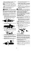
1. Loosen and remove both clamp screws.
2. Place the upper shoulder strap clamp
over the upper tube.
3. Position the lower shoulder s trap clamp
under the upper tube and align the upper
and lower clamp screw holes.
Upper Shoulder
Strap Clamp
Screws
Lower Shoulder
Strap Clamp
POWERHEAD
END
ATTACHMENT
END
4. Insert two screws into the screw holes.
5. Secure shoulder strap clamp by tighten-
ing screws with a hex wrench.
ADJUSTING THE ASSIST HANDLE
WARNING:
When adjusting the as-
sist handle, be sure it remains between the
coupler and the
lower arrow (closest to
coupler) on the safety label to ensure proper
balancing of unit. When adjusting the assist
handle or handlebar during use of optional at-
tachments, it must be repositioned between
the throttle trigger and the
upper arrow
(closest to engine) on the safety label.
1. Loosen wing nut on handle.
2. Rotate the handle on the tube to an up-
right position; ret ighten wing nut.