


20
REAR DEFLECTOR (IF EQUIPPED)
The rear defl ector, attached between the
rear wheels of your mower, is provided to
minimize the pos si bil i ty that objects will
be thrown out of the rear of the mower
into the operator mowing position. If the
defl ector becomes dam aged, it should be
replaced.
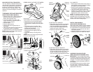
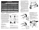
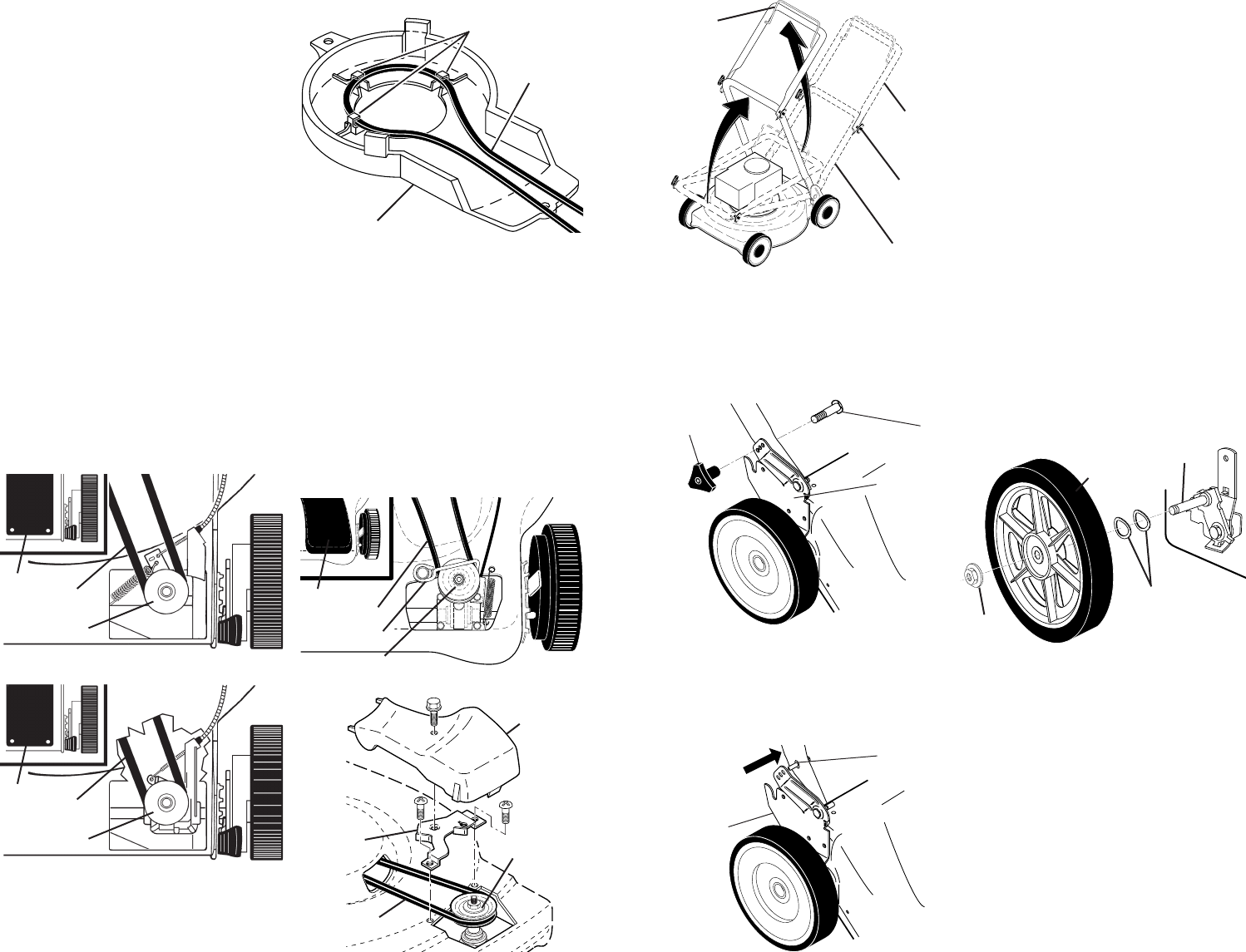
TO REMOVE / REPLACE DRIVE BELT
FRONT WHEEL DRIVE MODELS:
• Remove drive cover. Remove belt from
gearcase pulley by pushing down on
pulley and rolling belt off it.
• Turn lawn mower on its side. See
engine manual for proper direction of
turning over the engine.
• Remove blade.
• Remove debris shield.
• Remove belt from engine pulley on
crankshaft.
• Place new drive belt in the belt retainers
of the debris shield (if equipped).
• Install new belt by reversing above steps.
NOTE: Always use factory approved belt
to assure fi t and long life.
Belt
Drive
cover
PUSH DOWN
Belt
Drive
cover
PUSH DOWN
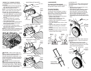
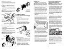
GEAR CASE WITH PLASTIC HOUSING:
GEAR CASE WITH METAL HOUSING:
“AUTO WALK” OR “VARI-SPEED” ONLY
• Remove drive cover and belt keeper.
• Remove belt from gearcase pulley by
push ing down on pulley and rolling belt
off it.
• Turn lawn mower on its side. See
engine manual for proper direction of
turning over the engine.
• Remove blade and debris shield.
• Remove belt from engine pulley on
crankshaft.
• Install new belt by reversing above
steps.
NOTE: Always use factory approved belt
to assure fi t and long life.
Debris shield
Drive belt
Belt retainers
DEBRIS SHIELD WITH BELT RETAINERS:
Belt
Drive
cover
PUSH DOWN
Belt keeper
Belt
Drive
cover
PUSH
DOWN
Belt
keeper
“TORUS” HOUSING ONLY:
5
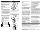
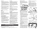
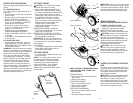
3 POSITION “QUICK” HANDLES
• Raise lower handle section to operating
position and squeeze the bottom ends
of lower handle towards each other until
the pin in handle can be inserted into
one of the three height adjustment holes.
3 POSITION “EZ” HANDLES
• Raise lower handle section to operating
position and align hole in handle with
one of three height positioning holes.
• Insert handle bolt through handle and
bracket and secure with knob.
• Repeat for opposite side of handle.
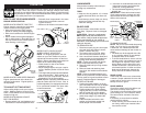
Flanged
locknut
Wheel
assembly
Wave
Washers
Axle
Handle
ad just ment
brack et
Knob
Bolt
Handle pin
Handle
ad just ment
bracket
SQUEEZE
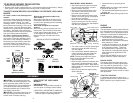
ALL HANDLES
• Raise upper handle section into place on
lower han dle, remove protective padding
and tighten both handle knobs.
• Remove handle padding holding opera-
tor pres ence control bar to upper handle.
• Your lawn mower handle can be ad-
justed for your mowing comfort. Refer to
“ADJUST HANDLE” in the Service and
Adjustments section of this manual.
NOTE: For shipping purposes, the rear
wheels on your lawn mower may not be
adjusted to the same position as the front
wheels. Before operating mower adjust all
wheels to the same cutting height.
INSTALL REAR WHEELS
(HIGH WHEEL MOWERS ONLY)
Some high wheel models require wash ers
which will be pro vid ed in a parts bag. If provid-
ed, install washers on the axle fi rst as shown.
• Install one (1) rear wheel on the axle of
rear wheel adjuster.
• Install 3/8-16 locknut and tighten securely.
• Repeat procedure for other rear wheel.
MOWING
POSITION
Lower handle
LIFT
UP
Operator
presence
control bar
Upper
handle
LIFT
UP
Handle
knob
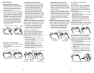
AS SEM BLE GRASS CATCHER
(REAR DISCHARGE MOWERS ONLY)
IMPORTANT: If your model lawn mower
is mulcher ready, the mulcher plate or plug
must be removed before using mower as
a bagger. To convert mower to bagging or
discharging, see the Operation section in
this manual.
Look at the different grass catcher illustra-
tions that follow. Determine which type
of grass catcher you have and follow the
appropriate instructions.