


7
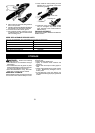
6. Before using the unit, tighten both knobs
securely by turning clockwise.
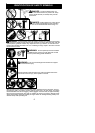
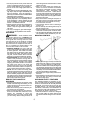
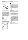
WARNING: Make sure the locking/
release buttonis locked in t heprimary holeof
both couplers and the knobs are securely
tightened before operating the unit. Usi ng the
wrong holes could lead toserious injury or dam-
age to the unit.
Locking/Release
Button in Primary Hole
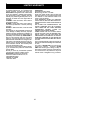
SHOULDER ST RAP ASSEMBLY
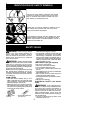
WARNING: Proper shoulder strapand
handle adjustments ar e required before use.
The shoulder strap clamp must be installed as
shown above the assist handle on the engine
end shaft.
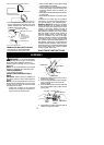
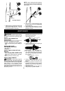
NOTE: The lower shoulder strap clamp has
two spacer tabs attached. These tabs are
providedto adaptthis attachmentfor usewith
units that have a 1 inch (2,5 cm) diameter
shaft (theshoulderstrapclampwill nottighten
downsecurely onthe1inch(2,5cm)diameter
shaft without using these spacer tabs). The
tabs must be broken off completely before
use and placed over the screw holes on the
lower shoulder strap clamp. These tabs are
not neededfor units witha 7/8″(2,2 cm)shaft.
Spacer Tabs
LOWER SHOULDER ST RAP
CLAMP
Spacer Tabs
positioned for use
on 1 inch (2,5 cm)
diameter shaft
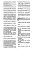
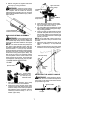
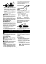
1. Place the upper shoulder strap clam p
over the shaft above the handlebar.
2. Position the lower shoulder strap clamp
under the upper shaft and align the upper
andlowerclampscrew holes (usespacer
tabs between upper and lower clamps if
necessary to secure clamp, i.e. for 1″ di-
ameter upper shaft).
Upper Shoulde r
Strap Clamp
Screws
Lower Shoulder
Strap Clamp
ENGINE/MOTOR
END
ATTACHMENT
END
3. Insert two screws into the screw holes.
4. Secure shoulder strap clamp by tighten-
ing screws with the hex wrench.
5. Try on shoulder strap and adjust for fit and
balance before starting the e ngin e or begi n-
ning a cutting operation.
6. Insertyourrightarm andhead throughthe
shoulder strap and allow it to rest on your
left shoulder. Make sure the danger sign
is onyour back andthehook is to theright
side of your waist.
NOTE: A one-half twist is built in the shoul-
der strap to allow the strap to rest flat on the
shoulder.
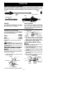
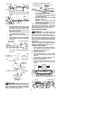
7. Adjust the strap, allowing the hook to be
about 3 -- 6 inches (8 -- 15 cm) below the
wai st.
8. Fasten the strap hook to the upper clamp
and lift the tool to the operating position.
Shoulder Strap
Shoulder
Strap
Clamp
ADJUSTING THE ASSIST HANDLE
WARNING: When adjusting the as-
sist handle, be sure it remains directly above
the coupler on the engine endshaft to ensure
proper balancing of unit.
Assist Handle
Coupler