6
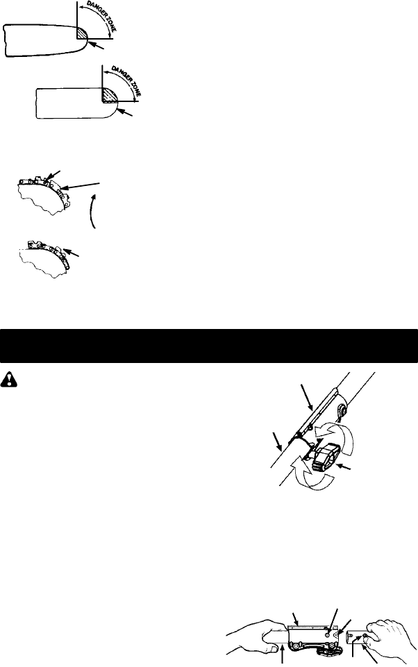
Small Radius Tip
Reduced KickbackSymmetrical Guide Bar
SymmetricalGuide Bar
Large Radius Tip
S Low--Kickback Chain,designedwith acon-
toured depth gauge and guard link which
deflect kickback force and allow wood to
gradually ride into the cutter.
Low--- Kickback
Chain
Not a Low---Kickback Chain
Can Obstruct Material
Contoured Depth Gauge
Elongated Guard Link
Deflects
kickback force
and allows wood
to gradually ride
into cutter
TRANSPORTING AND STORAGE
S Do not grasp or hold exposed blade.
S Stop unit before leaving work area.
S Allow unit and gearbox to cool before storing
or transporting it in a vehicle.
S Store unit and fuel in area where fuel vapors
cannot reach sparks or open flames from wa-
ter heaters, electric motors or switches, fur-
naces, etc.
S Store attachment so b lade cannot accidental-
ly cause injury .
S Store attachment indoors, out of reach of chil-
dren.
If situations occur which a re not covered in
this manual, use care and good judgment. If
you need assistance, call 1-800-554-6723.
SPECIAL NOTICE: Exposure to vibrations
through prolonged use o f gasoline powered
hand tools could cause blood vessel or nerve
damage in the fingers, hands, and joints of
people prone to circulation disorders or abnor-
mal swellings. Prolonged use in cold weather
has been linked to b lood vessel damage i n
otherwise healthy people. If symptoms occur
such as numbness, pain, loss of strength,
change in skin color or texture, or loss of f eeling
in the fingers, hands, or joints, discontinue the
use of t his tool and seek m edical a ttentio n. An
anti-vibration system does not guarantee the
avoidance of these problems. Users who oper-
ate power tools on a continual and regular basis
must monitor closely their physical condition
and the condi tion of th is un it.
SAVE THESE INSTRUCTIONS
ASSEMBLY
WARNING: If received assembled,
repeat allsteps to ensure your unit isproperly
assembled and all fasteners are secure.
Examine parts for damage. Do not use dam-
aged parts.
NOTE: If you need assistance or find parts
missing or damaged, call 1-800-554-6723.
TOOLS REQUIRED
S Hex wrench (provided)
INSTALL ING PRUNER ATTACH-
MENT
CAUTION:
When removing or installing at-
tachments, place the unit on a flat surface for
stability.
NOTE: The pruner attachment connects to
the engine endshaft through use of a coupler
system. For extra reach, the extension shaft
(included) can be used.
1. Loosen the c ouplers on the extension
shaft and on the engineend shaft by turn-
ing the knobs counterclockwise.
Attachment
Coupler
Knob
LOOSEN
TIGHTEN
2. Remove the shaft cap from the pruner at-
tachment (if present).
3. Position locking/release button of attach-
ment into guide recess of coupler on
extension shaft.
4. Push the attachment intothe coupleruntil
the locking/release button snaps into the
primary hole.
Coupler
Primary Hole
Upper
Shaft
Locking/
Release
Button
Attachment
Guide Recess
5. Repeat steps to attach extension shaft to
coupler on engine end shaft.


