


5
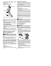
CONFIGURING YOUR UNIT
You can configure your unit using a cutting
head for grass and light weeds, or a weed
blade for cutting grass, weeds, and brush up
to 1/2 inch in diameter. To assemble your unit,
go to the section for the desired configuration
and follow the instructions.
ASSEMBLY INFORMATION --
TRIMMER HEAD
TRIMMER
HEAD
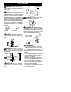
NOTE:
Remove the blade and m etal shield be-
fore attaching the plastic shield and trimmer
head. To remove blade, push in locking lever
and hold. Rotate blade nut until the locking lever
falls into one of the grooves in the dust cup.
Continue to hold the locking lever. This will keep
the shaft from turning while loosening the blade
nut. Remove b lade nut by tur ning clockw ise.
Release locking l ever. Remove both washers
and blade. To remove metal shield, l oosen and
remove the four mounting screws. See A T-
TACH ING THE METAL SHIELD and INSTAL-
LATION OF THE M ETAL BLAD E for illustra-
tions. Be sur e to store all par ts and instructions
for future use.
ATTACHING THE PLASTIC SHIELD
AND TRIMMER HEAD
WARNING:
The shield must be prop-
erly installed. The shield provides partial
protection to the operator and others from the
risk of thrown objects, and is equipped with a
line limiter blade which cuts excess line to the
proper length. The l ine limiter blade (on un-
derside of shield) is sharp and can cut you.
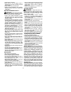
1. Remove wing nut from shield.
2. Insert bracket into s lot on shield.
3. Pivot shield until bolt passes through hole
in bracket.
4. Tighten the wing nut securely.
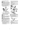
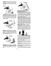
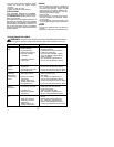
NOTE:
If your unit has a plastic cover over
the threads on the threaded shaft, remove the
covering to expose the threads. Before
installing the trimmer head, make sure the
dust cup is positioned on the gearbox as
shown below.
Wing Nut
Dust Cup
Bracket
Slot
Shield
Gearbox
NOTE:
Make sure all parts are properly
installed as shown in the illustration before
installing the trimmer head.
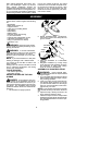
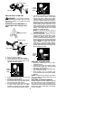
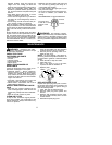
5. Push in locking lever and hold.
6. Rotate dust cup until the locking lever
falls into one of the grooves
.
Locking Lever
7. Continue to hold in locking lever. This will
keep the shaft from turning while tighten-
ing the trimmer head.
8. Thread trimmer head onto the shaft in the
direction shown o n the decal. Tighten un-
til secure.
9. Release locking lever.
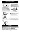
ASSEMBLY INFORMATION -- WEED
BLADE
WEED
BLADE
NOTE:
Remove the trimmer head and plas-
tic shield before attaching the metal shield
and installing one of the weed blades. To re-
move the trimmer head, push in locking lever
and hold. Rotate t rimmer head until the lock-
ing lever falls into one of the grooves in the
dust cup. Continue to hold in locking lever.
This will keep the shaft from turning while
loosening the cutting head. To remove the
plastic shield, loosen and remove wing nut.
Pivot shield to release bracket from slot. See
INSTALLATION OF THE CUTTING HEAD
and ATTACHING THE PLASTIC SHIELD for
illustrations. B e sure to store all parts and in-
structions for future use. Never use the trim-
mer head with the metal blade installed.