


5
S
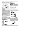
Adjust the handl ebar t o the proper position
and tighten the two screws you left loose
during handlebar assembly. Make sure
these screws are securely tightened.
S
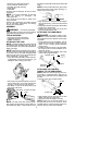
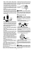
After attaching the control handle and tight-
ening the handlebar, route the wire from the
control handle through the slit in the bottom
of the foam grip.
Slit
Wire
Foam Grip
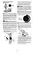
ASSEMBLY OF SHOULDER STRAP
WARNING:
Propershoulderstrapand
handlebar adjustments before starting the en-
gine are required.
S
Tr yon shoulder strap andadjust forfit andbal-
ance befor e starting the engineor beginninga
cutting operation.
S
Insert your right arm and head through the
shoulder strap andallow itto rest on yourleft
shoulder. Make sure the danger sign is on
your back and the hook is to the right side of
your waist.
NOTE:
A one-half twist isbuilt inthe shoulder
strap toallow the strap torest flat on the shoul-
der.
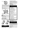
S
Adjust the strap, allowing t he hook to be
about 6 inches below the waist.
S
Fasten the strap hook to the clamp located
between the foam grip and the mounting
block and lift the tool to the operating posi-
tion.
CONFIGURING YOUR UNIT
You can configure your unit using a cutting
head for g rass and light weeds, or a brush
blade for cutting saplings and similar size ma-
terial. Go to the section for the desired
configuration and follow the instructions for
assembling your unit.
ASSEMBLY INFORMATION --
TRIMMER HEAD
TRIMMER
HEAD
NOTE:
If your unit has been assembled for
brushblade use, refer to the s ection AS-
SEMBLY I NFORMATION FOR USING
YOUR UNIT WITH A BRUSHBLADE and re-
verse the steps to remove the metal shield and
blade before you mount the plastic shield and
trimmer head.
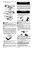
ATTACHING THE PLASTIC SHIELD
AND TRIMMER HEAD
WARNING:
The shield m ust be prop-
erly installed. The shield p rovides par tial protec-
tion from the risk o f thrown objects to the oper a-
tor and others and is equipped with a line limiter
which cuts excess line to the proper length. The
line limiter (on underside of shield) is sharp and
can cut you.
S
Remove wing nut from shield.
S
Insert bracket into slot on shield.
S
Pivot shield until bolt passes through hole in
bracket.
S
Tighten the wing nut securely.
S
If yourunithas a plastic coverover thethreads
on the threaded shaft, remove the covering to
expose the thr eads.
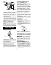
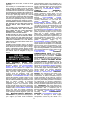
S
Before installing the trimmer head, make
sure the dust cup and retaining washer are
positioned on the gearbox as shown below.
Wing Nut
Retaining W asher
Dust Cup
Bracket
Slot
Shield
Gearbox
NOTE:
Make sure all parts are properly
installed as illustrated in the illustration before
installing the trimmer head.
S
Align hole inthe dust cup with the hole inthe
side of the gearbox by rotating the dust cup.
S
Insert a hex wrench into aligned holes. This
will keep the shaft from turning while tighten-
ing the trimmer head.
Hex Wrench
S
While holding the hex wrench in position,
thread trimmer head onto theshaft andtight-
en until secure.
NOTE:
The retaining washer must be posi-
tioned with the raised section facing toward
the gearbox.