


4
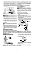
S
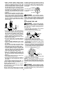
shield for use with trimmer head
S
semi-automatic trimmer head
S
shoulder strap with warning
S
brush blade
S
handlebar
Examine parts for damage. Do not use dam-
aged parts.
NOTE:
If you need assistance o r find that
parts are missing or damaged, call
1-800-554-6723.
It is normal for the fuel filter to rattle in the
empty fuel tank.
Finding fuel or oil residue on muffler is normal
due to carburetor adjustments and testing
done by the manufacturer.
ASSEMBLY
WARNING:
If received as sembled,
repeat all steps to ensure your unit is properly
assembled and all fasteners are secure.
TOOLS REQUIRED
S
2 hex key wrenches (provided)
S
adjustable wrench or large pliers
S
phillips screwdriver
ATTACHING THE TUBE
NOTE:
Illustr a tion s with in th is sec tion will help
in identifying the assembly steps. Be sure to
rea d each section and review the illustration s ,
before you begin.
NOTE:
Adrive shaft islocated in the center of
the tube. Make sure this shaft does not fall out
of the tube. Dirt on the shaft will significantly
reduce the life of the unit. If this shaft falls out,
clean, relubricate , and re-install.
S
Insert the 2 tube assembly screws and nuts
as illustrated. Keep loose at this time, you
will tighten them during a later step.
S
Some units may include aplastic coverover
the end of the tube. If your unit includes any
covering, remove the cover at this time.
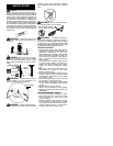
S
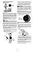
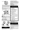
Pull about 1/2 inch of the drive shaft out of
the inside of the tube.
Pull about 1/2 inch from tube
Tube
NOTE:
The end of the drive shaf t i s squar e.
This square end f its i nside a squar e hole in a
shaft i nside the engine. Look inside the end of
theengine andyouwill seethe squarehole inthe
sha ft.
NOTE:
The end of the tube has agroove that
aligns with a ridge in the engine opening. Lo-
cate the groove and ridge.
GrooveRidge
S
Align the groove in the tube with the r idge in
the engine opening. Insert the tube into the
opening.
S
Firmly push the tube into engine until i t will no
longer go into the opening.
S
Tighten the screws, using one of the hex
keys provided with the uni t.
ATTACHING THE HANDLEBAR
DANGER:
The barrier portion of the
handlebar must be isntalled as shown to pro-
vide a barrier between operator and the spin-
ning blade.
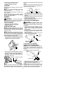
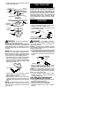
S
Locate the decal on the handlebar. This de-
cal includes two arrows. Position t he han-
dlebar on the mounting bracket between
these arrows.
S
Position the b racket cover over the handle-
bar. Again make sure the handlebar is be-
tween the arrows.
S
Insert screws and hand tighten only. These
screws will be tightened later.
Bracket Cover
Screw
Mounting
Bracket
Handlebar
ATTACHING THE CONTROL
HANDLE TO THE HANDLEBAR
NOTE:
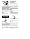
Make sure the wire going to the con-
trol handle i s routed below the tube and re-
mains o n the right side of the handlebar and
the tube.
S
Remove screw from control handle.
Screw Hole
Screw
S
Slide handle onto t he right side of the han-
dlebar and align the screw hole.
S
Re-insert screw and tighten s ecurely.
NOTE:
Make sure the control handle is on
the right side of the unit as shown in the il-
lustration below, and the On/Stop switch is lo-
cated on the top of the control handle.