


9
ASSEMBLY
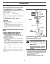
• Push cap over end of bagger dump handle.
NOTE: For future use, the clevis pin may be removed in order
to use the handle to clear the chute in the event it has become
clogged.
FIG. 5C
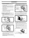
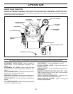
BAGGER ADJUSTMENT (See Fig. 6 & 7)
For proper bag function and appearance, it may be nec-
es sary to adjust the bagger assembly. There should be 6mm
(1/4")-9mm (3/8") gap between the bagger top and fender
and the bagger top surface should be even with the top
surface of the fender. To adjust bagger position:
HORIZONTAL ADJUSTMENT
• Slightly loosen the nuts securing the bagger RH and
LH hor i zon tal adjustment brackets. Loosen only enough
so the brackets keep their position, but allow them to
be moved.
• Move the brackets the amount forward or back ward you
wish the bag assembly to move. Retighten the nuts
securely.
VERTICAL ADJUSTMENT
• Slightly loosen the nuts securing the vertical adjust-
ment brackets. Loosen only enough so the brackets
keep their position, but allow them to be moved.
• Move the brackets the amount up or down you wish the
bag assembly to move. Retighten the nuts securely.
• Reinstall the bagger as sem bly and check the bagger
to fender fi t. If necessary, repeat the procedure until
proper fi t is attained.
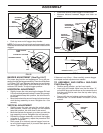
• After proper fi t is attained, remove bagger from trac-
tor and install bagger latch (4) to tractor back plate as
shown. Tighten securely.
TO ASSEMBLE AND INSTALL MULCHER
PLUG (See Fig. 8)
• Remove spring retainer and pin from handle.
• Insert plug into handle. Make sure that the letter "A"
on both the plug and handle are on the same side and
that they can both be seen from the top when laying
on the ground.
• Secure with pin and retainer spring provided. For in-
stal la tion see "To Convert Mower" in Section 5 of this
manual.
02214
A
A
HAN DLE
PIN
RE TAIN ER
SPRING
PLUG
FIG. 6
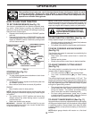
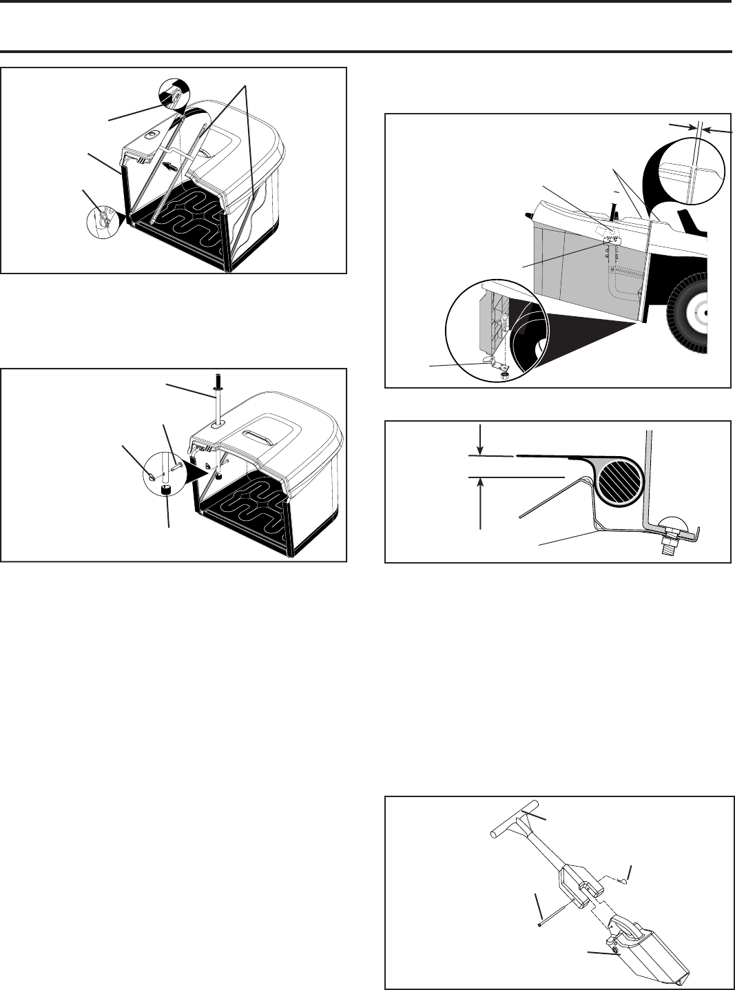
• Install and carefully lower bagger to actuate latch.
• Measure distance between bagger and latch as
shown.
029
06
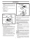
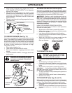
RETAINER SPRING
SPREADER BARS
RETAINER
SPRING
VINYL
BINDING
If distance is not 10mm - 16mm carefully remove bagger
and repeat vertical adjustment as needed.
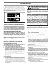
FIG. 5B
02907
DUMP HANDLE
TUBE
CLEVIS PIN 10 X 44MM
RETAINER SPRING
CAP
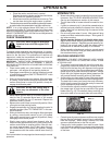
FIG. 7
02967
TOP SURFACES
EVEN
6MM (1/4") - 9MM (3/8")
HORIZONTAL
ADJUSTMENT
BRACK ET
VERTICAL
ADJUSTMENT
BRACK ET
BAGGER
LATCH
FIG. 7
02983
10MM (7/16") - 16MM (5/8")
BAGGER LATCH
FIG. 8