


8
ASSEMBLY
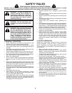
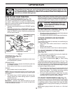
• Sit on seat in operating position, depress clutch/brake
pedal and set the parking brake.
• Place motion control lever in neutral (N) position.
• Press lift lever plunger and raise attachment lift lever
to its highest position.
• Remove key from bag and start the engine (see "TO
START ENGINE" in the Operation section of this man-
ual). After engine has started, move throttle control to
idle (slow) position.
• Release parking brake.
• Slowly move the mo tion control lever for ward and slowly
drive tractor off skid.
• Apply brake to stop trac tor, set park ing brake and place
motion con trol lever in neutral po si tion.
• Turn ignition key to "STOP" position.
Continue with the in struc tions that follow.
FIG. 4D
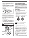
• Replace discharge chute into rear opening of tractor.
Secure the chute with the two hook straps.
02306
HOOK
BACKPLATE
SLOT
DIS CHARGE
CHUTE
FIG. 5A
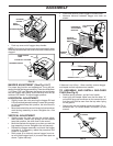
TO ASSEMBLE BAGGER (See Figs. 5A-5C)
• Unfold bag by pivoting front bagger tube all the way
forward and pressing the bottom vinyl binding onto the
tube.
• Inside the bag, install spreader bars and retainer springs
onto pins on both sides of bag as shown.
• Press the vinyl bindings onto the sides of front bagger
tube.
• Slide the bagger dump handle through the hole in the
bagger top, install the clevis pin 10 x 44mm and secure
with retainer spring.
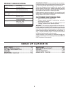
FIG. 4B
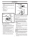
• Using the nuts and fl at washers removed from tractor
back plate, install the bagger support tube to the back
plate as shown. Tighten securely.
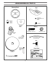
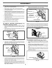
• Install the two upper support brack ets through the back
plate and to the chas sis, install the clevis pin 10x17mm
and secure with retainer spring.
• Assemble both support brackets to the outside of the
bagger support tube using two each 3/8 x 63,5mm hex
bolts13/32" I.D. fl at washers and 3/8 locknuts from parts
bag. Tight en securely.
02330
SUP PORT
TUBE
FLAT
WASHER
3/8 NUT
BOLT
FIG. 4C
030
28
CLEVIS PIN 10 X 17MM
3/8 LOCK NUT
SUPPORT BRACKET
10,3MM (13/32")
FLAT WASHER
3/8 X 63,5MM HEX BOLT
RETAINER SPRING
029
0
5
VINYL BINDING
FRONT BAGGER TUBE
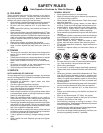
FIG. 4A
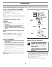
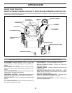
TO INSTALL BAGGER COM PO NENTS TO
TRAC TOR (See Figs. 4A-4D)
• Remove discharge chute from rear of tractor. Unhook
the two (2) straps and pull chute out and away from
tractor.
• Remove the two (2) 3/8 nuts and fl at washers from the
bolts at the tractor back plate.
02277
DISCHARGE
CHUTE
3/8 NUT
FLATWASHER
NOTE: The strap hook must go through the discharge chute
only. Do not allow the hook to enter the slot in the tractor
back plate. This will allow the dis charge chute to fl oat with the
mower deck when moving on uneven terrain.