


24
02232_Hydro
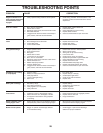
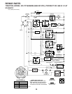
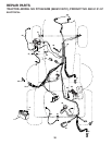
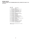
SERVICE AND ADJUSTMENTS
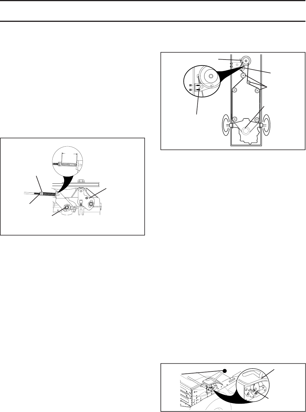
FIG. 30
FIG. 31
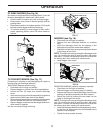
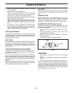
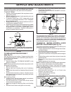
WITH PARKING BRAKE “ENGAGED”
JAM NUT
DO NOT TOUCH THIS NUT. IF FURTHER BRAKE AD JUST MENT
IS NECESSARY CONTACT YOUR NEAREST AUTHORIZED SER-
VICE CENTER/DEPARTMENT
OPERATING
ARM
NUT “A”
1-9/16"
02239
ADJUSTMENT
BOLT
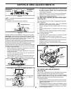
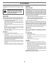
FIG. 32
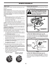
NEUTRAL
LOCK
GATE
MOTION CONTROL
LEVER
TRANSAXLE MOTION CONTROL LE VER
NEUTRAL ADJUSTMENT(See Fig. 32)
The motion control lever has been pre set at the factory and
adjustment should not be necessary.
• Loosen adjustment bolt in front of the right rear wheel,
and lightly tighten.
• Start engine and move motion control lever until tractor
does not move forward or backward.
• Hold motion control lever in that position and turn engine
off.
• While holding motion control lever in place, loosen the
adjustment bolt.
• Move motion control lever to the neutral (N) (lock gate)
position.
• Tighten adjustment bolt securely.
NOTE: If additional clearance is needed to get to ad just ment
bolt, move mower deck height to the lowest position.
After above adjustment is made, if the tractor still creeps
forward or backward while motion control lever is in neutral
position, follow these steps:
• Loosen the adjustment bolt.
• Move the motion control lever 1/4 to 1/2 inch in the
direction it is trying to creep.
• Tighten adjustment bolt securely.
• Start engine and test.
• If tractor still creeps, repeat above steps until satisfi ed.
TRANSMISSION REMOVAL/REPLACEMENT
Should your transmission require removal for service or
replacement, it should be purged after reinstallation and
before operating the tractor. See “PURGE TRANS MIS SION”
in the Operation section of this manual.
The rear wheels must lock and skid when you try to manually
push the tractor forward. If the rear wheels rotate, the brake
needs to be adjusted or the pads need to be replaced.
TO ADJUST BRAKE
• Depress clutch/brake pedal all the way down and en-
gage parking brake.
• Measure distance between brake operating arm and
nut “A” on brake rod.
• If distance is other than 1-9/16", loosen jam nut and
turn nut “A” until distance becomes 1-9/16". Retighten
jam nut against nut “A”.
• Engage transmission by placing freewheel control in
“trans mis sion engaged” position.
• Road test tractor for proper stopping distance as stated
above. Readjust if nec es sary. If stopping distance is
still greater than fi ve (5) feet in high est gear, further
main te nance is nec es sary. Replace brake pads or
contact a qualifi ed service center.
02379
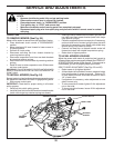
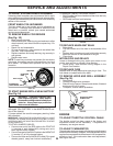
CLUTCH
STA TION ARY
IDLER
CLUTCH ING
IDLER
CLUTCH
LOCATOR
FAN
TO REPLACE MOTION DRIVE BELT
(See Fig. 31)
Park the tractor on level surface. En gage parking brake.
For as sis tance, there is a belt installation guide decal on
bottom side of left footrest.
BELT REMOVAL -
• Remove mower (See “TO RE MOVE MOWER” in this
section of manual).
NOTE: Observe entire motion drive belt and position of all
belt guides and keepers.
• Remove clutch locator.
• Remove belt from clutching idler and all stationary
idlers.
• Remove belt downward from engine pulley and around
clutch.
• Pull belt slack toward rear of trac tor. Carefully remove
belt up wards from trans mis sion input pulley and over
cooling fan blades.
BELT INSTALLATION -
• Carefully work new belt down around transmission
cool ing fan and onto the input pulley.
• Pull belt toward front of tractor and roll belt around
clutch and onto engine pulley.
• Install belt through all stationary idlers and clutch ing
idler.
• Reinstall clutch locator and tighten nut securely.
• Make sure belt is in all pulley grooves and in side all
belt guides and keep ers.
• Install mower (See “TO IN STALL MOWER” in this sec-
tion of manual).