


23
01156
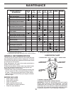
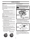
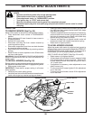
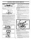
TO REPLACE MOWER BLADE DRIVE BELT
(See Fig. 29)
Park the tractor on level surface. Engage parking brake.
BELT REMOVAL -
• Remove mower from tractor (See “TO REMOVE
MOW ER” in this section of this manual).
• Remove screws from RH mandrel cover and remove
cover.
• Remove screws from LH mandrel cover and remove
cover.
• Work belt off both mandrel pulleys and idler pulleys.
• Pull belt away from mower.
BELT INSTALLATION -
• Install new belt in reverse order of removal. See belt
routing decal located on right mandrel cover.
• Make sure belt is in all pulley grooves and in side all
belt guides.
• Install left and right mandrel covers and tighten se cure ly.
Make sure belt is in mandrel pulley cover.
• Install mower (see "To install mower" in this section of
this manual).
SERVICE AND ADJUSTMENTS
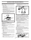
NUT "E"
01268
"D""D"
MANDREL
FIG. 27
NUT "F"
FRONT LINKS
FIG. 28
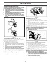
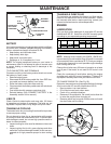
FRONT-TO-BACK ADJUSTMENT (See Figs. 27 and 28)
IMPORTANT: DECK MUST BE LEVEL SIDE-TO-SIDE. IF THE
FOLLOWING FRONT-TO-BACK ADJUSTMENT IS NECESSARY,
BE SURE TO AD JUST BOTH FRONT LINKS EQUAL LY SO
MOWER WILL STAY LEVEL SIDE-TO-SIDE.
To obtain the best cutting results, the mower housing should
be adjusted so that the front is approximately 1/8" to 1/2" lower
than the rear when the mower is in its highest position.
Check adjustment on right side of tractor. Measure dis tance
“D” directly in front and behind the mandrel at bottom edge
of mower housing as shown.
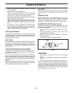
• Before making any necessary adjustments, check that
both front links are equal in length.
• If links are not equal in length, adjust one link to same
length as other link.
• To lower front of mower loosen nut “E” on both front
links an equal number of turns.
• When distance “D” is 1/8" to 1/2" lower at front than rear,
tighten nuts “F” against trunnion on both front links.
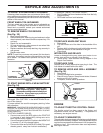
BOTH FRONT LINKS MUST BE EQUAL IN LENGTH
01267
FIG. 25
01553
SUSPENSION ARM
LIFT LINK ADJUSTMENT NUT
FIG. 26
00598
“A”
“A”
BOTTOM EDGE
OF MOWER
TO GROUND
BOTTOM EDGE
OF MOWER
TO GROUND
GROUND LINE
TRUNNION
FIG. 29
LH MANDREL COVER
IDLER
PULLEY
BELT
MANDREL
PULLEY
IDLER PULLEY
RH MANDREL
COVER
MANDREL
PULLEY
NOTE: Three full turns of adjustment nut will change mower
height about 1/8".
• Recheck measurements after adjusting.
TO CHECK AND ADJUST BRAKE
(See Fig. 30)
Your tractor is equipped with an ad just able brake system
which is mounted on the right side of the transaxle.
If tractor requires more than fi ve (5) feet to stop at highest
speed in high est gear on a level, dry concrete or paved
surface, then brake must be checked and ad just ed.
TO CHECK BRAKE
• Park tractor on a level, dry concrete or paved surface,
depress clutch/brake pedal all the way down and en-
gage parking brake.
• Disengage transmission by placing freewheel control
in “transmission disengaged” position. Pull freewheel
con trol out and into the slot and release so it is held in
the disengaged position.
• To raise front of mower, loosen nut “F” from trunnion
on both front links. Tighten nut “E” on both front links
an equal number of turns. The two front links must
remain equal in length.
• When distance “D” is 1/8" to 1/2" lower at front than rear,
tighten nut “F” against trunnion on both front links.
• Recheck side-to-side adjustment.