


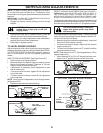

23
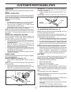
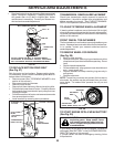
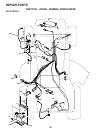
TO REMOVE WHEEL FOR REPAIRS
(See Fig. 28)
• Block up axle securely.
• Remove axle cover, retaining ring and washers to allow
wheel removal (rear wheel contains a square key - Do not
lose).
• Repair tire and reassemble.
• On rear wheels only: align grooves in rear wheel hub and
axle. Insert square key.
• Replace washers and snap retaining ring securely in
axle groove.
• Replace axle cover.
NOTE: To seal tire punctures and prevent flat tires due to
slow leaks, tire sealant may be purchased from your local
parts dealer. Tire sealant also prevents tire dry rot and
corrosion.
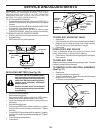
TO START ENGINE WITH A WEAK BATTERY
(See Fig. 29)
CAUTION: Lead-acid batteries generate
explosive gases. Keep sparks, flame
and smoking materials away from bat-
teries. Always wear eye protection when
around batteries.
If your battery is too weak to start the engine, it should be
recharged. (See "BATTERY" in the CUSTOMER RESPON-
SIBILITIES section of this manual).
If “jumper cables” are used for emergency starting, follow
this procedure:
RETAINING
RING
WASHERS
AXLE
COVER
SQUARE KEY
(REAR WHEEL ONLY)
FIG. 28
TRANSMISSION REMOVAL/REPLACEMENT
Should your transmission require removal for service or
replacement, it should be purged after reinstallation and
before operating the tractor. See “PURGE TRANSMIS-
SION” in the Operation section of this manual.
SERVICE AND ADJUSTMENTS
TO ADJUST STEERING WHEEL ALIGNMENT
If steering wheel crossbars are not horizontal (left to right)
when wheels are positioned straight forward, remove steer-
ing wheel and reassemble per instructions in the Assembly
section of this manual.
FRONT WHEEL TOE-IN/CAMBER
The front wheel toe-in and camber are not adjustable on your
tractor. If damage has occurred to affect the front wheel toe-
in or camber, contact your nearest authorized service
center/department.
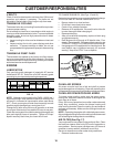
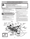
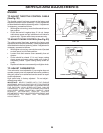
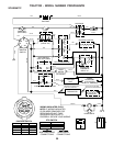
FIG. 27
CLUTCH LOCATOR
CLUTCH
WIRE HARNESS
STATIONARY
IDLER
TRANSMISSION
INPUT PULLEY
CLUTCHING
IDLER
ELECTRIC
CLUTCH
FIG. 26
TO REPLACE MOTION DRIVE BELT
(See Fig. 27)
Park the tractor on level surface. Engage parking brake.
For assistance, there is a belt installation guide decal on
bottom side of left footrest.
• Remove mower (See “TO REMOVE MOWER” in this
section of this manual.)
• Disconnect clutch wire harness.
• Remove clutch locator.
• Remove belt from stationary idler and clutching idler.
• Pull belt slack toward rear of tractor. Carefully remove
belt upwards from transmission input pulley and over
cooling fan blades.
• Pull belt toward front of tractor and remove downwards
from around electric clutch.
• Install new belt by reversing above procedure.
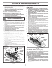
• Road test tractor for proper stopping distance as stated
above. Readjust if necessary. If stopping distance is
still greater than six (6) feet in highest gear, further
maintenance is necessary. Contact your nearest au-
thorized service center/department.
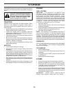
WITH PARKING BRAKE “ENGAGED”
JAM NUT
DO NOT TOUCH THIS NUT. IF FURTHER BRAKE
ADJUSTMENT IS NECESSARY CONTACT YOUR NEAR-
EST AUTHORIZED SERVICE CENTER/DEPARTMENT
OPERATING
ARM
NUT “A”
1-3/4"