


20
SERVICE AND ADJUSTMENTS
CAUTION: BEFORE PERFORMING ANY SERVICE OR ADJUSTMENTS:
• Depress brake pedal fully and set parking brake.
• Place attachment clutch in “DISENGAGED” position.
• Turn ignition key “OFF” and remove key.
• Make sure the blades and all moving parts have completely stopped.
• Disconnect spark plug wire from spark plug and place wire where it cannot come in contact
with plug.
TRACTOR
FIG. 19
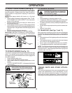
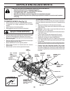
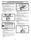
TO REMOVE MOWER (See Fig. 19)
• Place attachment clutch in “DISENGAGED” position.
• If equipped, turn height adjustment knob to lowest
setting.
• Lower mower to its lowest position.
• Disengage belt tension rod from lock bracket.
CAUTION: Rod is spring loaded. Have a
tight grip on rod and release slowly.
• Remove retainer spring holding anti-swaybar to chassis
bracket and disengage anti-swaybar from bracket.
• Remove four retainer springs from front plate assembly
and remove plate.
• Remove retainer springs from suspension arms at deck
and disengage arms from deck.
• Raise attachment lift to its highest position.
• Slide mower forward and remove belt from electric
clutch pulley.
• Slide mower out from under right side of tractor.
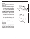
TO INSTALL MOWER
Be sure tractor is on level surface and mower suspension
arms are raised with attachment lift control. Engage parking
brake.
• Swing anti-sway bar to left side of mower deck.
• Slide mower under tractor with deflector shield to right
side of tractor.
IMPORTANT: CHECK BELT FOR PROPER ROUTING IN
ALL MOWER PULLEY GROOVES.
• If equipped, turn height adjustment knob counterclock-
wise until it stops.
• Lower mower linkage with attachment lift control.
• Be sure belt tension rod is in disengaged position.
• Install belt into electric clutch pulley groove.
• Place the suspension arms on outward pointing deck
pins. Retain with double loop retainer spring with loops
up as shown.
• Install front plate assembly to tractor suspension brack-
ets and retain with single loop retainer springs as shown.
• Position front plate assembly between front mower
brackets. Raise deck and plate assembly to align holes
and insert flanged pins. Secure pins with double loop
retainer springs between the plate assembly and mower
brackets.
SUSPENSION
ARMS
RETAINER
SPRING
ANTI-SWAY
BAR
SUSPENSION ARMS
DOUBLE LOOP
RETAINER SPRINGS
(Outward pointing
deck pins)
CHASSIS
BRACKET
SINGLE LOOP
RETAINER
SPRING
FRONT
MOWER
BRACKET
FLANGED PIN
ELECTRIC
CLUTCH
PULLEY
FRONT
PLATE
ASSEMBLY
BELT TENSION
ROD
(DISENGAGED
POSITION)
DOUBLE LOOP
RETAINER
SPRING
DEFLECTOR
SHIELD
LOCK
BRACKET
USE PLIERS FOR
RETAINER SPRINGS
LOOP UP