


21
SERVICE AND ADJUSTMENTS
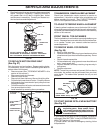
MANDREL
FIG. 22
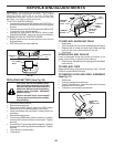
FIG. 23
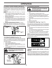
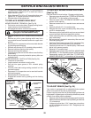
FIG. 21
LIFT LINK
ADJUSTMENT NUT
SUSPENSION ARM
BOTH FRONT LINKS MUST BE EQUAL IN LENGTH
TRUNNION
FRONT
PLATE
ASSEMBLY
NUT “C”
NUT “D”
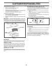
FRONT-TO-BACK ADJUSTMENT (See Figs. 22 and 23)
IMPORTANT: DECK MUST BE LEVEL SIDE-TO-SIDE. IF
THE FOLLOWING FRONT-TO-BACK ADJUSTMENT IS
NECESSARY, BE SURE TO ADJUST BOTH FRONT LINKS
EQUALLY SO MOWER WILL STAY LEVEL SIDE-TO-SIDE.
To obtain the best cutting results, the mower blades should
be adjusted so the front tip is approximately 1/8" to 1/2" lower
than the rear tip when the mower is in its highest position.
CAUTION: Blades are sharp. Protect your
hands with gloves and/or wrap blade
with heavy cloth.
Check adjustment on right side of tractor. Position any blade
so the tip is pointing straight forward. Measure distance "B"
at front and rear tip of the blade.
• Before making any necessary adjustments, check that
both front links are equal in length.
• If links are not equal in length, adjust one link to same
length as other link.
• To lower front of blade, loosen nut “C” on both front links
an equal number of turns.
NOTE: Each full turn of nut “C” will change distance. “B” by
approximately 3/16".
• When distance “B” is 1/8" to 1/2" lower at front than rear,
tighten nut “D” against trunnion on both front links.
“B”
“B”
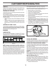
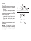
TO LEVEL MOWER HOUSING
Adjust the mower while tractor is parked on level ground or
driveway. Make sure tires are properly inflated (See “PROD-
UCT SPECIFICATIONS” section of this manual). If tires are
over or underinflated, you will not properly adjust your
mower.
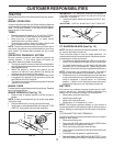
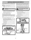
SIDE-TO-SIDE ADJUSTMENT (See Figs. 20 and 21)
• Raise mower to its highest position.
• Measure height from bottom edge of mower to ground
level at front corners of mower. Distance “A” on both
sides of mower should be the same.
• If adjustment is necessary, make adjustment on one
side of mower only.
• To raise one side of mower, tighten lift link adjustment
nut on that side.
• To lower one side of mower, loosen lift link adjustment
nut on that side.
NOTE: Each full turn of adjustment nut will change mower
height about 3/16".
• Recheck measurements after adjusting.
BOTTOM EDGE
OF MOWER TO
GROUND
BOTTOM EDGE
OF MOWER TO
GROUND
A
A
GROUND LINE
FIG. 20
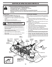
NOTE: To assist in locating hole in flanged pin, the hole in
pin is inline with notch on head of pin. If necessary, move
mower side-to-side to give space between plate and mower
brackets.
IMPORTANT: CHECK BELT FOR PROPER ROUTING IN
ALL MOWER PULLEY GROOVES.
• Engage belt tension rod by pushing rod into locking
bracket.
CAUTION: Belt tension rod is spring
loaded. Have a tight grip on rod and
engage slowly.
• Connect anti-sway bar to chassis bracket under left
footrest and retain with double loop retainer spring.
• If equipped, turn height adjustment knob clockwise to
remove slack from mower suspension.
• Raise deck to highest position.