


22
SERVICE AND ADJUSTMENTS
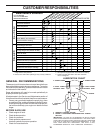
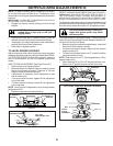
L.H.
MANDREL
CENTER
MANDREL
IDLER
PULLEY
R.H.
MANDREL
COVER
SPRING
FIG. 25
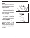
TO ADJUST BRAKE (See Fig. 26)
Your tractor is equipped with an adjustable brake system
which is mounted on the side of the transaxle.
If tractor requires more than six (6) feet stopping distance at
high speed in highest gear on a level dry concrete or paved
surface, then brake must be adjusted.
• Depress clutch/brake pedal and engage parking brake.
• Measure distance between brake operating arm and nut
“A” on brake rod.
• If distance is other than 1-3/4", loosen jam nut and turn
nut “A” until distance becomes 1-3/4". Retighten jam nut
against nut “A”.
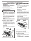
TO REPLACE MOWER BLADE DRIVE BELT
(See Fig. 25)
Park the tractor on level surface. Engage parking brake.
• Remove mower drive belt (See “TO REPLACE MOWER
DRIVE BELT” in this section of this manual).
• Remove mower (See “TO REMOVE MOWER” in this
section of this manual).
• Remove screws from L.H. mandrel cover and remove
cover.
• Carefully roll belt off L.H. mandrel pulley.
• Remove belt from center mandrel pulley, idler pulley,
and R.H. mandrel pulley.
• Remove any dirt or grass which may have accumulated
around mandrels and entire upper deck surface.
• Check secondary idler arm and idler pulley to see that
they rotate freely.
• Be sure spring is hooked in secondary idler arm and
secondary spring arm.
• Install new belt in lower groove of R.H. mandrel pulley,
idler pulley, and center mandrel pulley as shown.
• Carefully roll belt over L.H. mandrel pulley. Make sure
belt is in all grooves properly.
• Reinstall L.H. mandrel cover.
• Reinstall mower to tractor (See “INSTALL MOWER AND
DRIVE BELT” in the Assembly section of this manual).
• Reassemble mower drive belt (See “TO REPLACE
MOWER DRIVE BELT” in this section of this manual).
SECONDARY
IDLER ARM
SECONDARY
SPRING ARM
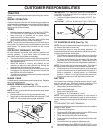
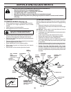
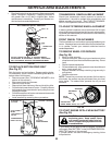
TO REPLACE MOWER DRIVE BELT
MOWER DRIVE BELT REMOVAL (See Fig. 24)
• Park tractor on a level surface. Engage parking brake.
• Lower mower to its lowest position.
• Disengage belt tention rod from lock bracket.
FIG. 24
• Remove screws from R.H. mandrel cover and remove
cover.
• Remove any dirt or grass clippings which may have
accumulated around mandrels and entire upper deck
surface.
• Disconnect R.H. suspension arm from rear deck bracket
by removing retainer spring.
• Roll belt over the top of R.H. mandrel pulley carefully.
• Remove belt from electric clutch pulley.
• Remove belt from idler pulleys.
• Check primary idler arm and two idlers to see that they
rotate freely.
• Be sure spring is securely hooked to primary idler arm
and spring arm.
MOWER DRIVE BELT INSTALLATION (See Fig. 24)
• Install belt in both idlers.
• Install new belt onto electric clutch pulley.
• Roll belt into upper groove of R.H. mandrel pulley
carefully.
• Carefully check belt routing making sure belt is in the
grooves correctly.
• Reconnect R.H. suspension arm to rear deck bracket
with retainer spring.
• Reassemble R.H. mandrel cover.
• Engage belt tension rod by pushing rod into locking
bracket.
CAUTION: Rod is spring loaded. Have a
tight grip on rod and release slowly.
PRIMARY
IDLER ARM
R.H.
MANDREL
IDLER
PULLEY
ELECTRIC
CLUTCH
PULLEY
SPRING
ARM
BELT
TENSION ROD
(DISENGAGED
POSITION)
RH MANDREL
COVER
RH
SUSPENSION
ARM
IDLER
PULLEY
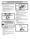
• To raise front of blade, loosen nut “D” from trunnion on
both front links. Tighten nut “C” on both front links an
equal number of turns.
• When distance “B” is 1/8" to 1/2" lower at front than rear,
tighten nut “D” against trunnion on both front links.
• Recheck side-to-side adjustment.