


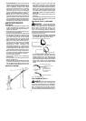
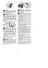
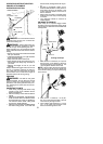
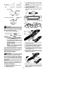

17
30˚
75˚
60˚
Rounded
Corner
0.025 inch
(0.65 mm)
Right
Hook Angle
Wrong
Squared O
f
f
Corner
Too M uch Hook
A
ngle
WARNING: Maintain the p roper hook
angle accordingto the manufacturer’s specifica-
tions for the chain you are using. Improper hook
angle will increase the chance of kickback
which can result in serious injury.
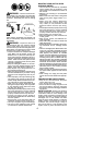
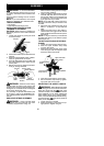
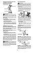
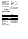
4. Check and lower depth gauges.
Depth Gauge To ol
Depth Gauge
File
S Pl a ce gauge tool on cutter.
S If the depth gauge is higher than the
depth gauge tool, file i t level t o the top of
the depth gauge tool.
S Maintainroundedfrontcornerofdepth
gauge with a flat file.
NOTE: The very top of the depth
gauge should be flat with the fronthalf
rounded off with a flat file.
If you require further assistance or are unsure
about performing this procedure, contact your
authorized service dealer or call our customer
assistance help line at 1--800--554--6723.
CHAIN REPLACEMENT
WARNING: Wear protective gloves
when handling chain. The chain is sharp and
can cut you even when it is not moving.
It is normal for a new chain to stretch during the
first 15 minutes of operation. You should re-
check your chain tension frequently and adjust
the chain tensionas required. See CHAIN TEN-
SION sectio n.
Replace the ol d chain when it becomes worn or
damaged. Use only t he Low-Kickback replace-
ment chain specified in the repair parts list.
TO REPLACE CHAIN:
1. Disconnect p runer fr om power source.
2. Remove bar clamp nut.
3. Remove bar clamp.
4. Turn adjusting screw by hand counter-
clockwise until adjusting pin just touches
the stop.
5. Slide guide bar behind sprocket until
guide bar stops against sprocket.
6. Remove the old chain.
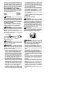
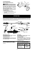
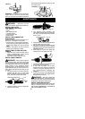
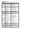
7. Carefully remove new chain from pack-
age. Hold chain with the drive links as
shown.
CUTTERS MUST FACE IN
DIRECTION OF R OTATION
Tip of
Bar
Cutter
Drivelink
Cutters
Depth Gauge
Drive Links
8. Placechainover sprocket,fitting thedrive
links in the sprocket.
9. Fit bottom of drive links bet ween the t eeth in
the sprocket in the nose of the guide bar .
10. Fit chain dr ive links into bar groove.
11. Pull guide bar forward until chain is snug
inguide bar groove. Ensureall drivelinks
are in the bar gr oove.
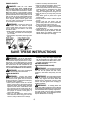
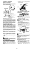
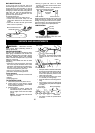
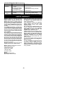
12. Now, install bar clamp making sure the
adjusting pin is positioned in the lower
hole in the guide bar.
Adjusting Pin
Lower
Hole
Guide Bar
13. Install bar clamp nut and finger tighten
only. Do not tighten any further at this
point. Proceed t o the CHAIN ADJUST-
MENT section.