


10
ASSEMBLY
WARNING: If received assembled,
review all assembly steps to ensure your unit
is properly assembled and all fasteners are
secure.
Examine parts for damage. Do not use dam-
aged par ts.
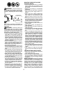
NOTE: If you need assistance or find parts
missing or damaged, call 1- 800 -554-6723.
TOOLS REQUIRED
S Hex wrench
S Chain adjustment tool (bar tool)
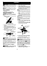
INSTALLING PRUNER OR LINE
TRIMMER ATTACHMENT
CAUTION:
When removing or installingat-
tachments, place the unit on a flat surface for
stability.
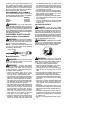
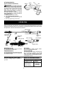
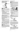
1. Loosen the coupler by turning the knob
counterclockwise.
Coupler
Knob
LOOSEN
TIGHTEN
2. Remove the shaft cap from attachment(if
present).
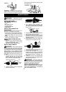
3. Position locking/release button of attach-
ment int o guide recess of coupler.
4. Push the attachment intothe coupleruntil
the locking/release but ton snaps into t he
primary hole.
5. Beforeusing theunit, tightenthe knobse-
curely by turning clockwise.
Coupler Primary Hole
Upper
Shaft
Locking/
Release
Button
Lower
Attachment
Guide Recess
WARNING: Make sure the locking/
release button is locked in the primary hole
and the knob is securely tightened before op-
erating theunit. Allattachments aredesigned
to be used in the primary hole.
For assembly of optional attachments (see
list on page 7), refer to the ASSEMBLY sec-
tion of the applicable attachment instruction
manual.
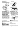
SHOULDER STRAP ASSEMBLY
WARNING: Proper shoulder strap
adjustments must be made with the motor
completely stopped before using unit .
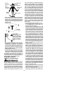
1. Try onshoulderstrapandadjustfor fitand
balance before starting the unit or begin-
ning a cutting operation.
2. Insertyour rightarm andheadthroughthe
shoulder strap and allow it torest on your
left shoulder. M ake sure the danger sign
is centered on your back and the hook is
to the right side of your waist.
NOTE: A one-half twist is built in the shoul-
der strap to allow the strap to rest flat on the
shoulder.
3. Adjust the strap, allowing the hook to be
about 3 -- 6 inches (8 -- 15 cm) below the
wai st.
4. Fasten the strap hook to the clamp lo-
cated between the trigger handle and the
assist handleandliftthe tooltotheoperat-
ing position.
NOTE: It may be necessary to relocate the
shoulder strap clamp on the shaft for proper
balancing of unit.
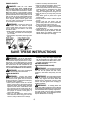
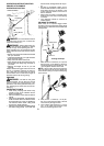
TO RELOCATE SHOULDER STRAP
CLAMP:
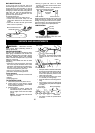
1. Loosen and remove both clamp screws.
2. Place the upper shoulder strap clamp
over the upper shaft.
3. Position the lower shoulder strap clamp
under the upper shaft and align the upper
and lower clamp screw holes.
Upper Shoulder
Strap Clamp
Screws
Lower Shoulder
Strap Clamp
POWERHEAD
END
ATTACHMENT
END
4. Insert two screws into the screw holes.
5. Secure shoulder strap clamp by tighten-
ing screws with a hex wrench.
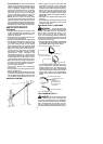
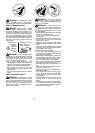
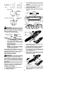
ADJUSTING THE ASSIST HANDLE
WARNING: Whenadjusting t he assist
handle during pruner use, be sureit remains be-
tween the coupler and t he
lower arrow
(closest to coupler) on the safety label to ensure
proper balancing of unit. When adjusting the
assist ha ndle during u se of optional a ttach-
ments, it must be repositioned be tween t he trig-
ger switch and the
upper arrow (closest to
motor) on the safety label.
1. Loosen w ing nut on handle.
2. Rotate the handle on the shaft to an up-
right position; retighten w ing nut.