


9
ASSEMBLY
WARNING: If received assembled,
repeatall steps toensure your unitis properly
assembled and all fasteners are secure.
Examine parts for damage. Do not use dam-
aged parts.
NOTE: If you need assistance or find parts
missing or damaged, call 1-800-554-6723.
It is normal for the fuel filter to rattle in the
empty fuel tank.
Finding fuelor oil residue onmuffler isnormal
due to carburetor adjustments and testing
done by the m anufacturer.
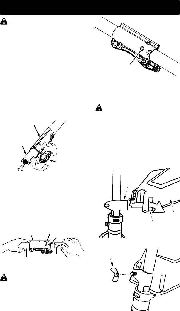
INSTALLING TRIMMER ATTACH-
MENT
CAUTION: When installingtrimmer attach-
ment,placetheunit onaflatsurface f orstabil-
ity.
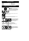
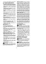
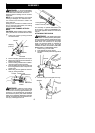
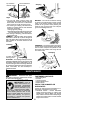
1. Loosen the coupler by turning the knob
counterclockwise.
Shipping
protector
Coupler
Knob
LOOSEN
TIGHTEN
2. Remove shipping protector fromcoupler.
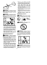
3. Remove the shaft cap f rom the trimme r at-
tachment (if present).
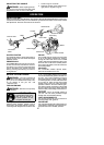
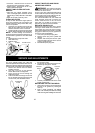
4. Position locking/release button ofattach-
ment into guide recess of coupler.
5. Pushtheattachment intothe coupleruntil
the locking/release button snaps into t he
primary hole.
6. Before using the unit, tighten the knob se-
curely by turning clo ckwise.
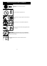
Coupler
Primary Hole
Upper
Shaft
Locking/
Release
Button
Attachment
Guide Recess
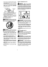
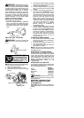
WARNING: Make sure the locking/
release button is locked in the primary hole
and theknob is securely tightened before op-
erating the unit. A ll at ta c hment s are d esigned
to be used in the primary hole unless otherwise
stated in the applicable attachment instruction
manual. Using thewrong holecouldlead toseri-
ous injury or damage to the unit.
Locking/Release
Button in Primary Hole
For assembly of optional attachments (see
list on page 11 ),refer to the ASSEMBLY sec-
tion of the applicable attachment instruction
manual.
ATTACHING THE SHIELD
WARNING: The shield m ust be p rop-
erly installed.The shield pro vides partialprotec-
tion from the risk ofthrown objects to the opera-
tor and others and is equipped with a line limiter
blade which cuts excess line to the proper
length. The line limiter blade (on underside of
shield) is sharp and can cut you. For proper
orientatio n of shield, see KNOW YOUR TRIM-
MER illustration in OPERA TION section.
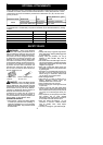
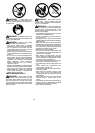
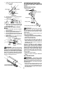
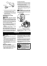
1. Remove wing nut from shield.
2. Insert bracket into slot as shown.
3. Pivot shield untilbolt passes through holein
bracket.
Bracket
Slot
Shield
4. Reinstall wing nut and tighten securely.
WingNut