


15
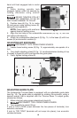
Loosen base locking screw and move motor unit up or down to
decrease or increase depth of cut.
It may be necessary with some bits to withdraw bit
from collet to obtain maximum depth of cut. When doing this be
sure at least
1
/2
" of bit shank is engaged in collet. Do not use bits
that result in having less than
1
/2
" of bit shank engaged in collet. To
do so may cause poor gripping of collet resulting in loose bit and
damage to work, or personal injury should the bit come out of collet.
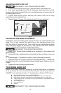
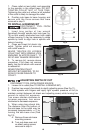
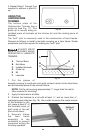
ADJUSTING TILT
1. Loosen two tilt locking screws (C) Fig. 6, (one on each side of base)
using wrench provided.
2. Tilt base aligning index mark (D) Fig. 6, with desired angle and tighten
securely.
3. Make a trial cut on scrap material to check alignment. Readjust if
necessary.
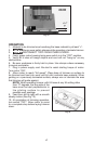
MODEL 7312 OFFSET TRIMMER ASSEMBLY
Model 7312 Offset Trimmer is completely assembled at the factory. The offset
base is assembled to Model 7301 Motor as outlined below. Model 7312
Offset Trimmer can be disassembled by reversing the following assembly
instructions.
ASSEMBLING OFFSET BASE TO MOTOR
DISCONNECT TOOL FROM POWER SOURCE.
1. Remove collet nut and collet from motor unit.
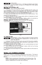
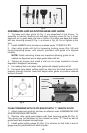
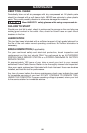
2. Assemble drive pulley (A) Fig. 7, to motor spindle and tighten securely.
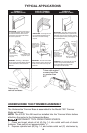
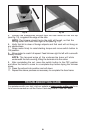
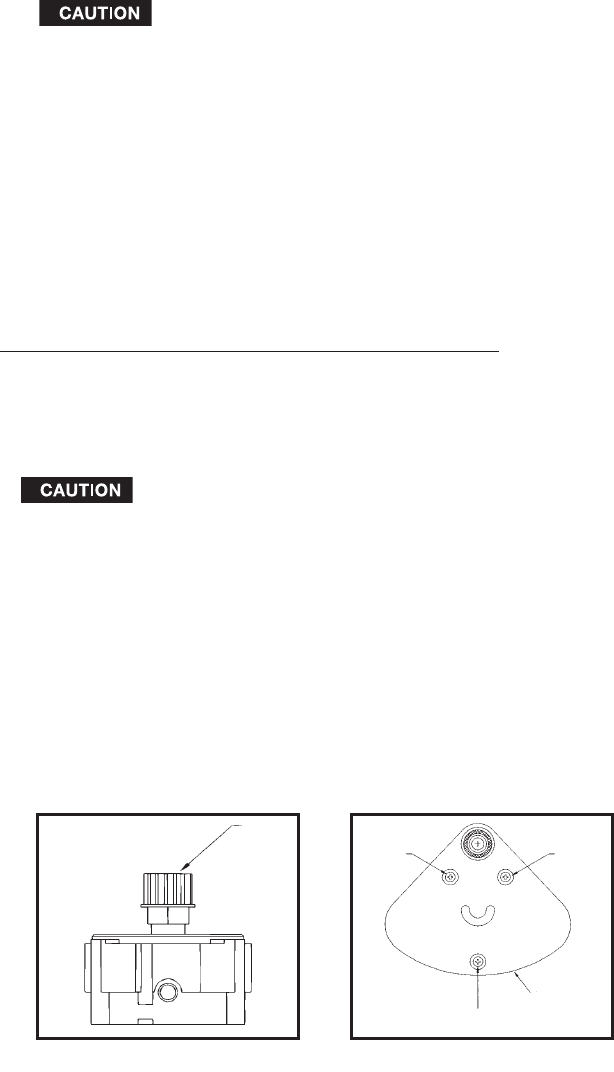
3. Use a phillips screwdriver to remove the three sub-base mounting
screws (A) Fig. 8, from the base, and remove the sub-base.
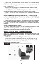
4. Position the base to the motor and drive pulley assembly (from
step 2). Be sure that the motor drive pulley engages the drive belt (inside the
base housing).
5. Secure the motor to the base (see Fig. 9), with the thumbscrew (A),
spring (B), and washer (C).
6. Locate the #6-32 ×
3
/8" screw from the hardware package. Use a phillips
screwdriver to install this screw (D), as shown in Fig. 9. Tighten securely.
A
A
A
A
SUB-BASE
Fig. 7
Fig. 8