


13
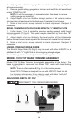
ASSEMBLING AND ADJUSTING BASE AND GUIDE
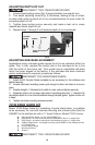
1. The base and roller guide (A) Fig. 4, are assembled at the factory. To
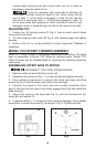
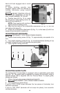
assemble to trimmer: Remove one sub-base mounting screw (A) Fig. 5, insert
alignment pin in guide base into hole in bottom of trimmer sub-base and fasten
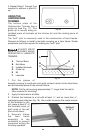
with two mounting screws (F) Fig. 4, as shown in Fig. 5A. Do not tighten at this
time.
2. Install 44858PC bit to trimmer as outlined under TO INSTALL BIT.
3. Align roller guide with bit by loosening locking screw (Fig. 5A) and
turning adjusting screw, with wrench provided, until guide is in desired
location.
NOTE: Guide mounting holes are oversized allowing guide to be
rotated on alignment pin to align guide roller with bit.
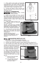
4. Tighten all screws and make a trial cut on scrap material to check
alignment. Readjust if necessary.
5. For making flush cuts align roller guide with straight portion of bit.
6. For bevel cuts adjust cutting depth so that only the bevel portion of bit
projects through trimmer base and adjust roller guide to produce desired
amount of bevel.
FLUSH TRIMMING WITH PILOTLESS BIT WITH
3
/8" LENGTH FLUTE
1. Attach base and guide to trimmer as outlined under ASSEMBLING AND
ADJUSTING BASE AND GUIDE.
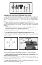
2. Remove roller guide and replace with flush trimming guide (B) (Fig. 4).
This guide may be identified by the molded on letter “F”. Stud on end of
guide must face towards trimmer base.
3. Install guide setting gauge (E) (Fig. 4) to trimmer so that hole in end of
gauge may be positioned over stud in guide.
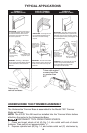
Fig. 4
ABCD EFG
ADJUSTING
SCREW
LOCKING SCREW
MOUNTING
SCREW
Fig. 5A
Fig. 5
A