


P/N • Núm/Pte. • Réf. 99360000 6 Rev. G • Rev. G • Rév. G 10-29-07
WARNING
Replace lamp with a similar type and wattage. Failure to replace lamp with the same type of lamp will damage the light
assembly and may cause an electrical hazard resulting in death or serious injury to pool users, installers, or others due
to electrical shock, and may also cause damage to property.
WARNING
Always install a new lens gasket (part number 79101600) whenever disassembling the light. Failure to do so may permit
water to leak into the assembly which could cause:
(a) an electrical hazard resulting in death or serious injury to pool users, installers or others due to electrical shock; or,
(b) breakage of the lamp or lens, which could result in serious injury to pool users, installers, bystanders, or in
property damage.
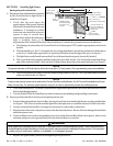
3. To remove light assembly, remove the special pilot screw at top of face ring, remove light assembly from niche,
and place assembly on deck.
WARNING
Be sure to keep the special pilot screw from this underwater light. This screw mounts and electrically grounds the
housing securely to the mounting ring and wet niche. Failure to use the screw provided could create an electrical hazard
which could result in death or serious injury to pool users, installers or others due to electrical shock.
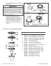
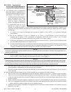
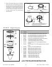
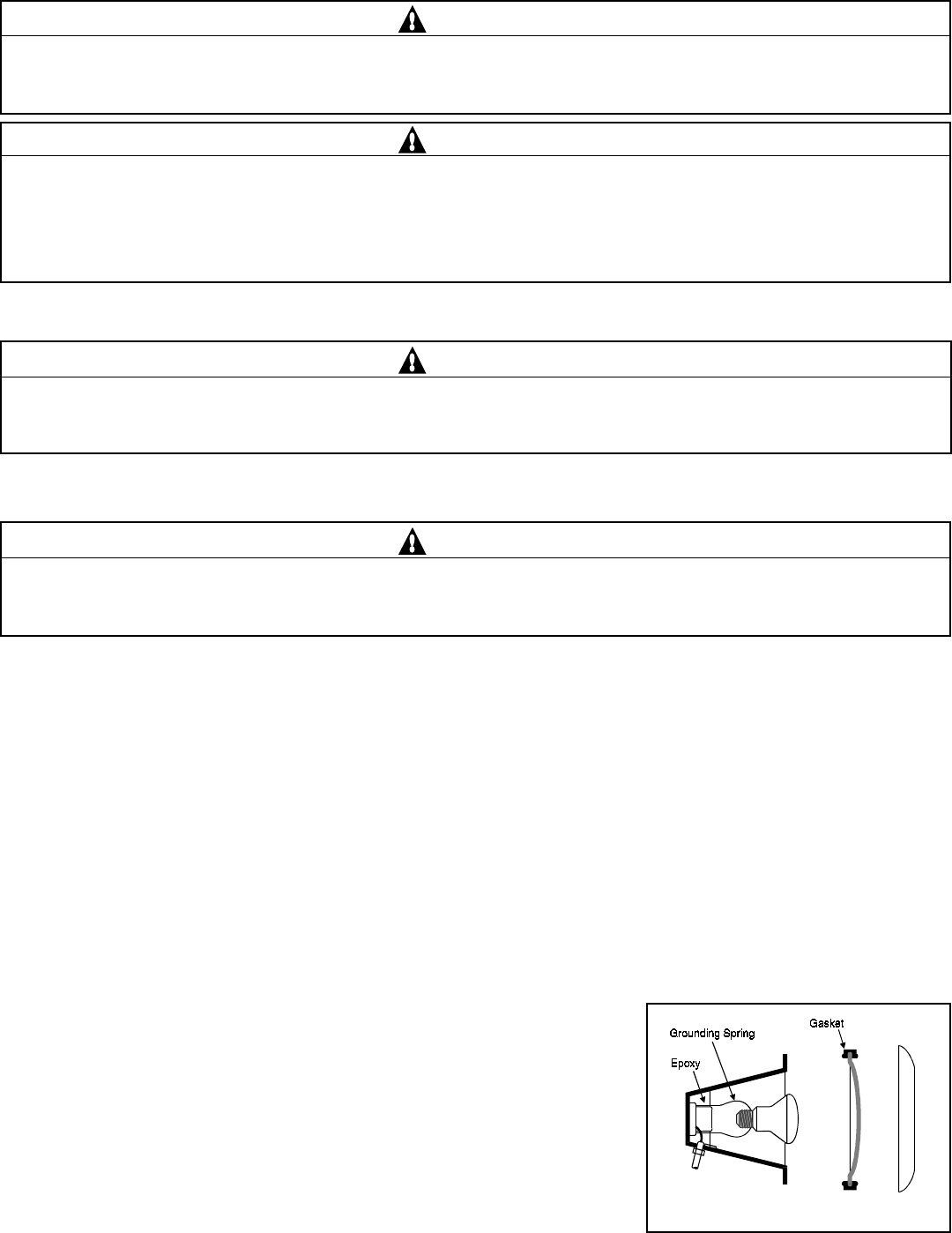
4. Disassemble light fixture and remove bulb. Remove and discard old gasket; see Figure 2.
5. Install new gasket during reassembly of light, Pentair Water Pool and Spa part number 79101600.
WARNING
Never operate the underwater light for more than 10 seconds unless it is totally submerged in water. Without total
submersion, the light assembly will get extremely hot and may result in serious burns or in breakage of the lamp or
lens. This may result in serious injury to pool users, installers, bystanders, or in damage to property.
6. Align the pilot screw on the face ring with the first “E” in the word “BEFORE” on the lens face. Then align the lens/
face ring assembly to the housing by lining up the pilot screw with the arrow on the warning label.
7. Secure ring to light fixture. Sealing screws must be tightened in the following manner to assure a proper seal;
a. For lights with chrome or brass face ring:
(1) Partly tighten the screw at the 12 o’clock position, and then partly tighten the screw at the 6 o’clock position.
Partly tighten the screw at another ‘opposite’ position, and then partly tighten the screw directly across
from it.
(2) Continue partly tightening all screws in the above sequence until all screws are evenly and securely tightened.
Recommended 20 inch pounds torque.
b.
For lights with stainless steel face ring:
(1) With the light resting on its base, align the face ring, and lens/gasket on top of the light shell as described in
Step 6. A NEW LENS GASKET MUST BE USED EACH TIME THE LIGHT IS REASSEMBLED.
The locking levers should all be hanging freely down to install over the lens and gasket. Before installing the
Unitension Clamp be sure that the gap at the ends of the clamp is
approximately 1 in. apart. Pull the ends of the Unitension Clamp
past one another to accomplish this.
(2) With the bent ends of the circular unitension clamp pointing
down spread the clamp and place it in the “U” recesses of the
locking levers. Be sure the bent ends of the clamp are located
between the pair of locking levers as shown in Figure 3,
location A. Check to see that the clamp is properly engaged
with all of the levers.
(3) Turn the light so that it is now resting on its lens. Tighten the bolt
and nut until the distance between the ends of the clamp equals 1/4 inch or less; see Figure 4.
Figure 2.