


Pelco Installation Manual C2432M-A (12/03) 5
INSTALLATION PENDANT MODELS
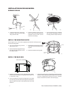
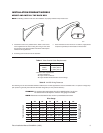
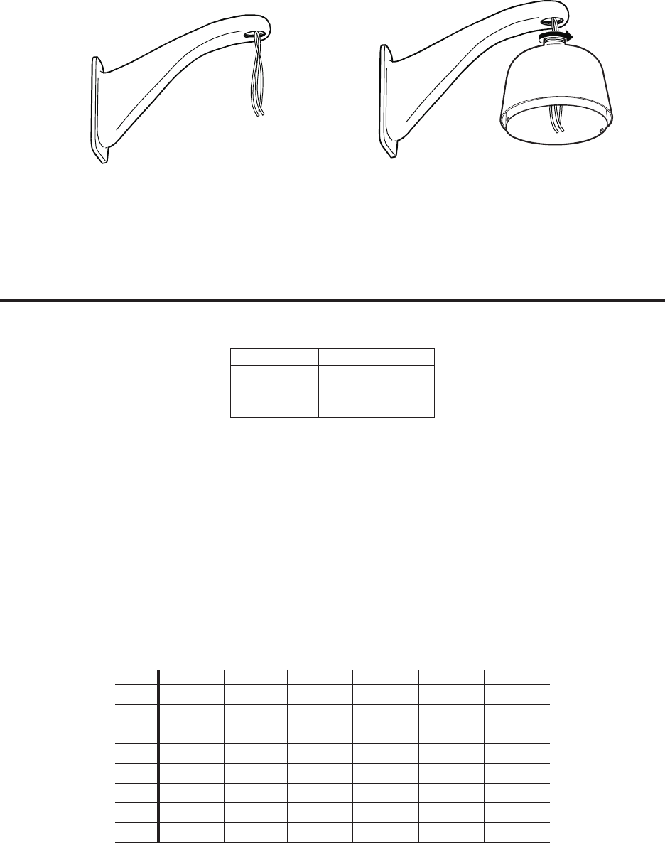
MOUNT AND INSTALL THE BACK BOX
NOTE: If installing outdoors make sure the installation is properly sealed to keep moisture out.
a. Install the mount for the pendant dome. Refer to the instruc-
tions supplied with the mount. Bring the wiring for the dome
through the mount. Refer to Tables A and B for cable require-
ments and wiring distances.
b. Pull wiring from the mount into the back box.
c. Screw the back box into the mount. If outdoors, apply thread
compound (provided) to the threads on the back box.
00540
00541
Table A. Video Coaxial Cable Requirements
Cable Type* Maximum Distance
RG59/U 750 ft (229 m)
RG6/U 1,000 ft (305 m)
RG11/U 1,500 ft (457 m)
* Minimum cable requirements:
75 ohms impedance
All-copper center conductor
All-copper braided shield with 95% braid coverage
Table B. 24 VAC Wiring Distances
The following are the recommended maximum distances for 24 VAC applications and are calculated with a 10-percent voltage drop.
(Ten percent is generally the maximum allowable voltage drop for AC-powered devices.)
EXAMPLE:
An enclosure that requires 80 vA and is installed 35 feet (10 m) from
the transformer would require a minimum wire gauge of 20 AWG.
NOTE:
Distances are calculated in feet; values in parentheses are meters.
20 18 16 14 12 10
10 283 (86) 451(137) 716 (218) 1142 (348) 1811 (551) 2880 (877)
20 141 (42) 225 (68) 358 (109) 571 (174) 905 (275) 1440 (438)
30 94 (28) 150 (45) 238 (72) 380 (115) 603 (183) 960 (292)
40 70 (21) 112 (34) 179 (54) 285 (86) 452 (137) 720 (219)
50 56 (17) 90 (27) 143 (43) 228 (69) 362 (110) 576 (175)
60 47 (14) 75 (22) 119 (36) 190 (57) 301 (91) 480 (146)
70 40 (12) 64 (19) 102 (31) 163 (49) 258 (78) 411 (125)
80 35 (10) 56 (17) 89 (27) 142 (43) 226 (68) 360 (109)
Wire Gauge
Total vA consumed
Maximum distance from
transformer to load