


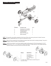
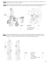
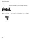
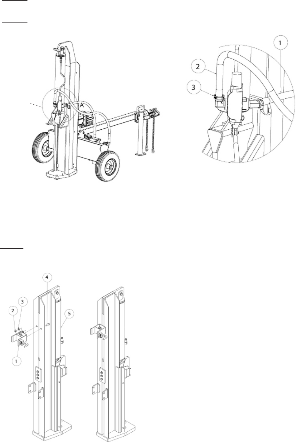
STEP 7: Loosely attach the latch assembly (1) to the bottom side of the beam as shown in the diagram using the
two1/2”x1-1/4”GR5hexcapbolts(4),thetwo1/2”lockwashers(3)andthetwo1/2”hexnuts(2).Lower
thebeamontothetongue.Centerthelatchassemblyonthetongueandtightenhardware.
Page 9
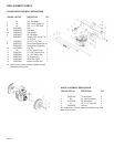
1 Beam Lock 1
2 1/2” Hex Nut 2
3 1/2” Lock Washer 2
4 1/2” x 1-1/4” GR5 Hex Cap Bolt 2
5 Beam Assembly 1
ITEM NO. DESCRIPTION QTY.
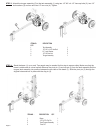
Area of
Detail
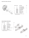
ITEM NO. DESCRPTION QTY.
1 1/2” X 38” Pressure Hose 1
2 3/4” x 56” Return Hose 1
3 Worm Gear Clamp 3
STEP 5: Connecttheendofthe1/2”IDx38”hydraulicpressurehose(1)comingfromthettingonthepumptothe
ttingonthevalve.Seeillustrationsbelow.
STEP 6: Slideonehoseclampontheendofthe1/2”x56”hydraulicreturnhose(2)thatcomesfromthettingonthe
lter.Thenconnectthehosetothettingonthevalve.Tightenhoseclamps.Seeillustrationsbelow.