


7
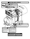
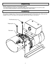
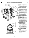
Machine Component Identification
1. Alternator. Also called generator
head.
2. Grounding Screw. Use to ground
the generator to a copper pipe or rod
that is driven into moist soil.
3. Isomounts. Reduces vibrations
transmitted to the control box
4. 30A Circuit Breaker. Thermal
magnetic breaker protects against
overcurrents and short circuits.
5. 120V Receptacles. One 120V 20A
straight blade receptacle duplex (two
receptacles in a common housing).
National Electrical Manufacturer’s
Association (NEMA) number 5-20R.
6. 20A Circuit Breaker. (Qty 2) Push
to reset style thermal breakers
protect against overcurrents.
7. 120/240V Locking Receptacle. 30A
receptacle, NEMA L14-30R.
8. Gearbox. 1:7 gear ratio.
9. Filler/Breather Plug. Fill oil here;
use SAE 80W-90 gear oil.
10. Implement shield. Never operate
generator without shield in place.
11. Fan Vents. Never block the vent
slots or insert objects through the
slots. The closest object should be
at least 3 feet away from the vents.
12. Mounting Holes. Use these
locations to mount the generator in
place with 5/8” grade 5 bolts.
13. Voltmeter. Needle should be in
green area during all generator load
conditions. The black line in the
center of the green area indicates
120V. During no load conditions,
the needle should be at or above the
black line.
14. 1-3/8” Diameter 6 Spline Input
Shaft. Requires 14 HP or greater at
540 RPM.
15. Oil Fill Sight Glass. When oil is
even with the red dot, the oil level is
correct. Check oil level daily.
16. Oil Drain Plug. Remove to drain oil
from gearbox.