


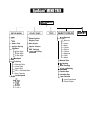

Linking
SynScanTM
SynScanTM.
SynScanT" 5i/8i
-
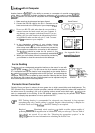
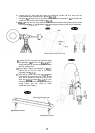
(Fig.p)
Cb53
com
a
I= EXPD+
2= -rD
3=
4=
5=
6= +12v
5i"
SynScan'"
more
information
on
SynScanrM
Fig.a,
I=
2=
3= +RA
Fig.q connectirlg
4= +DEC
5= -DEC
654321
6=
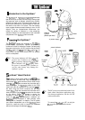
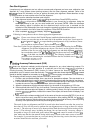
SynScanTM
SynScan"
acccssory: with
HEQ5lEQ6
with
A
Computer
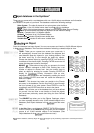
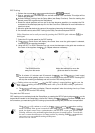
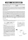
Another feature of is the ability to connect to a computer via a serial communication
cable. Many commercially available planetarium softwares can be used to control
Version 3.00 and later is compatible with Celestron
and NexStar GPS command
protocol.
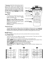
1. Make sure that the telescope has been aligned.
Hand Control
2.
Connect the RS
-
232 cable to the RJ
-
11 connector on the
hand control and to the COM
-
port of your computer
Do
not use RS
-
232 cable other than the one provided to
connect between the hand control and your computer. It
RJ
-
11
may damage your computer or the hand control. If you are
making your own cable based
on
the
information provided
in Appendix
B,
make sure that only pin 2, 3 and
5
connect
to the connector on your computer.
3. In the planetarium software of your choice, choose
"Celestron NexStar
or "Celestron 8/9/11 GPS" in the
driver setup menu and follow the instructions provided by
your program to establish the connection to the telescope.
The should be under the full control of your
RJ-11 Pin-outs
GND
EXPD
-
RD
654321
See Appendix
B
for
computer once the connection is successfully established.
4. When you are finished, follow the instructions provided by
RS
-
232 connection.
your software to close the connection to the telescope.
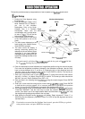
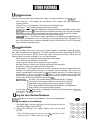
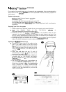
Auto Guiding
The has a designated autoguider interface on the mount for use with
NC
an auto guider (see
a
-
I). The pin
-
outs on the
6
pin modular connector is
Ground
ST
-
4 compatible and can be used for most autoguiders on the market. Refer to
(left)
when
(up)
(down)
the autoguider cable to the SynScan
TM
and calibrating the
autoguider. Relay box can be added for extra protection. Note that the four inputs
are active
-
low, with internal pull
-
ups. Guiding speed can be adjusted using the
-
RA (right)
Auto Guide Speed function in the Setup Menu.
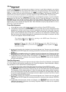
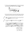
Periodic Error Correction
Periodic Errors are found in almost all worm gears due to slight eccentricities and misalignments. The
PEC (Periodic Error Correction) function provides a manual correcting method to reduce the amplitude of
the worm errors. By recording a full cycle of guiding actions versus motor shaft angle,
work to compensate for the drifting in the RA sidereal tracking caused by the periodic errors. Below
describes a step
-
by
-
step procedure on how to perform the PEC:
PEC
Training function is recommended for advanced users interested in long
-
exposure
astrophotograhy only. Careful guiding is required. Regular sidereal tracking is adequate for
all casual visual use of the
and
PEC
Training is not required.
Required Illuminated reticle eycpiccc
double crossline pattern capable of
producing at least 300X magnification in combination with your telescope. The true field of
view should not exceed 10 arc min. See
"
Choosing the appropriate eyepiece
"
in the
manual for more information on calculating the field of view.
can