GB - 16
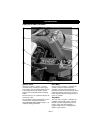
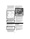
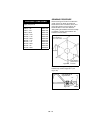
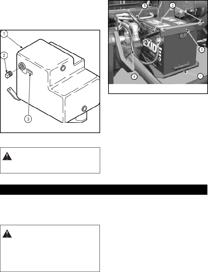
2. Check oil level by removing pipe plug (2,
Figure 13). The oil level should be at the
bottom edge of the hole, as indicated by
decal (3, Figure 13). If it becomes
necessary to add a small amount of oil
to the tank, it is added in the pipe plug
hole, possibly using a flexible spout
funnel.
Recommended oil is Chevron Rykon 100 or
Exxon Univus N100, or equivalent hydraulic
oil.
BATTERY
The 8400 is not shipped with a battery. A
group size 70, 12-volt side post battery is
recommended such as Exide model 70-LT-
60, which is approximately 7-3/16” high, 6-
3/4” wide and 8-5/8” long.
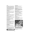
1. Place battery in battery holder (1,
Figure 14) with terminals facing the left
wheel. Insert the hook end of the battery
support rods (2, Figure 14) into holes on
the back vertical surface of the battery
holder.
2. Place battery hold down (3, Figure 14)
over support rods and upper corner of
battery and secure with flat washers and
hex nuts.
3. Attach the ground wire (4, Figure 14) to
the frame as shown. Connect the
ignition wire (5, Figure 14) to the positive
(+) terminal of the battery.
4. Attach the ground wire last to the
negative (–) terminal of the battery.
Read each instruction completely, and make
sure you understand it before making any
adjustments. Follow all the safety
precautions.
TRACTION PEDAL
ADJUSTMENTS
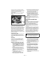
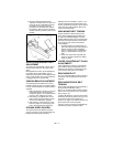
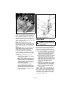
The traction pedal (1, Figure 15) is equipped
with a safety switch (2, Figure 15) and a
neutral centering device. The switch prevents
the engine from starting when the pedal is
positioned in reverse or forward. The
centering device locates neutral positioning of
the pump.
1. Prior to adjusting for creep, elevate the
wheels off the ground and support the
vehicle with jack stands. Any
adjustments should be done while the
hydraulic oil is warm.
2. To adjust the creep of the drive wheels,
loosen the fastener attaching the ball
bearing (3, Figure 15) to the control arm
(4, Figure 15), and move and secure the
bearing within the slot to achieve
neutral.
DANGER: Read and follow the
battery manufacturer’s instructions
on safety, maintenance and
installation procedures.
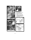
Figure 13
Figure 14
SERVICE AND ADJUSTMENTS
DANGER: To avoid possible
serious injury, before making any
adjustments or performing
maintenance, engage parking
brake, place all tractor controls in
neutral, lower cutting units to the
ground, turn ignition switch “off” and
remove key.


