07
SLIM-LINE RC
9.0 Commissioning Procedure
● Fill and vent the system.
● Open both valves fully and vent air from the heat exchanger
by unscrewing the air bleed valve situated above the valves in
the angled top of the chassis.
● Check for leaks at pipe connections.
● Refit the outer case and secure using the 2 fixing screws.
● Switch on electrical supply.
● Check the operation of the unit in automatic and manual
modes by following the operating instructions.
● When installation and commissioning are complete, hand over
instruction manual to end-user.
Heat Pump Applications - Low Water Set Point
Adjustment Heating Mode
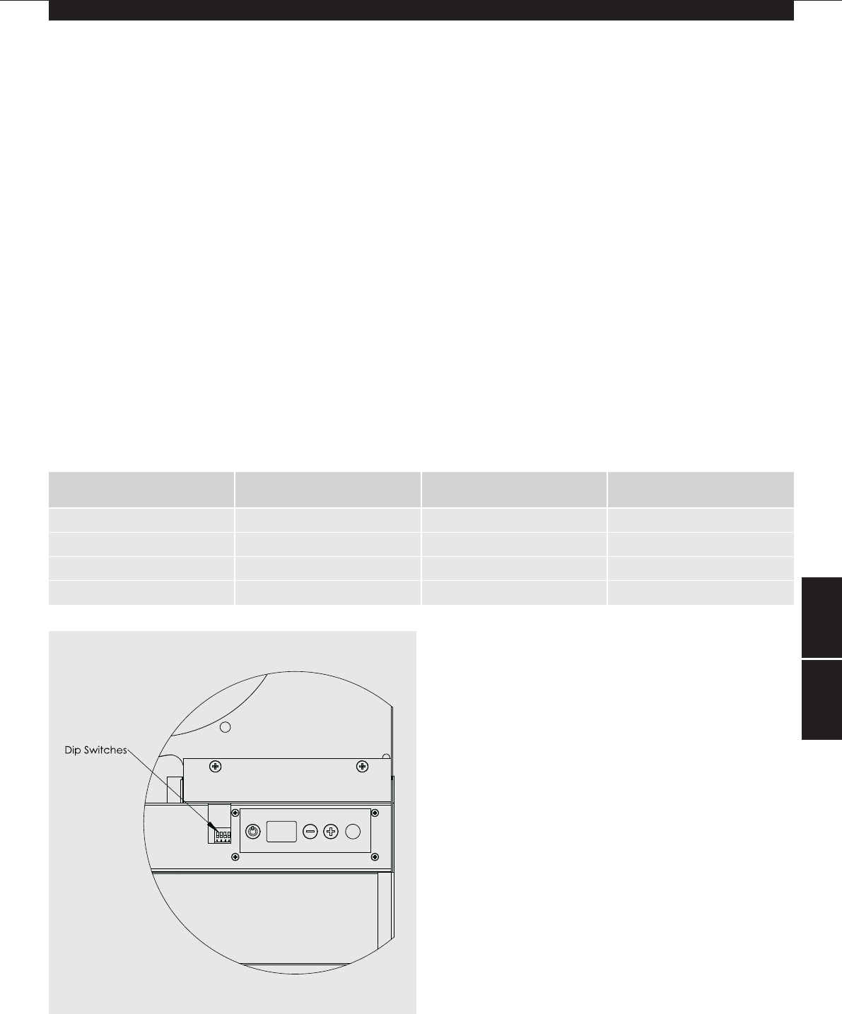
The low limit water set point is factory set to 43°C, but for
systems such as those with heat pumps, a lower water set point
may be required. The set point can be adjusted using the set
point dip switch located on the control board.
● Isolate electrical supply.
● Remove outer cover.
● Change switch position (see fig. 3).
● Refit cover.
● Switch on electrical supply.
Displayed Temperature Calibration
Depending on the location of the unit there may be a difference
between the temperature at the unit and the temperature in the
middle of the room being heated.
The displayed temperature calibration function enables
calibration in heating mode of the displayed temperature to the
actual room temperature using the following procedure:
● Press the ‘On/Off’ key and ‘+’ key for 5 seconds (the display
will flash, alternating between ‘ro’ and the calibration
temperature.
● Calibrate the displayed room temperature by using the
‘+’ and ‘-’ keys with the fan running.
● Press the ‘On/Off’ key to finish
Switch Switch Down Switch Up
1 Water Stat Set Point 32°C 43°C
2 Heating Heating Do not use
3 Not Used
4 Temperature Display °F °C
8.09.0
Fig. 3
22369 Slimline RC Manual:Layout 1 10/11/09 16:02 Page 8


