


Page 9
MACRO range installation manual. Issue 6
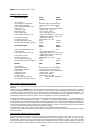
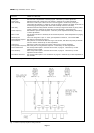
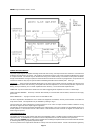
LINE INPUT MODULES L24 L25 L26 L27 L28 L29 L30 L31 L32 L33 L34
Transformer input or unbalanced T T T T T T T T T U U
Priority operation only """"""
Priority/passive switchable """ ""
Sensitivity 50mV - .775V "" "" "" ""
Sensitivity 50mV - 80V """
Input impedance (ohms) 600 10k 47k 600 10k 47k 600 10k 47k 4k7 4k7
Priority controlled sink """""""""""
Chimes """ "
Chime Duration Sink """
Audio activated priority (VOX) """
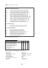
GENERAL SPECIFICATIONS - LINE INPUT MODULES
Sensitivity range and impedance See above
Frequency response -3dB points 20Hz - 18kHz
Signal to noise ratio 58dB minimum
Input overload capability 50dB
Sink capability (mA max. continuous) 250mA
VOX delay 3 seconds maximum
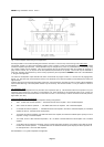
TONE GENERATORS T24 T25 T26 T27 T28 T30 T31 T32 T34
Momentary or timed triggering M T T T T M T T T
Adjustable tone frequency """"""""
Priority hold for tone sequence """" """
Priority memory """" ""
Adjustable duration timer """" """
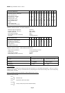
GENERAL SPECIFICATIONS - TONE GENERATOR MODULES
Trigger switch requirements 1.5mA maximum @ +15V DC
Duration timer 2 - 30 seconds approx
Trigger memory capacity Indefinite
Sink capability (mA max. continuous) 250mA
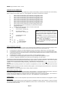
MISCELLANEOUS MODULES E26
Function Magnetic phono pre-amp Ceramic phono pre-amp
Sensitivity 5mV@50k 80mV-1V @ 1M
Equalisation RIAA Flat
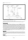
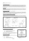
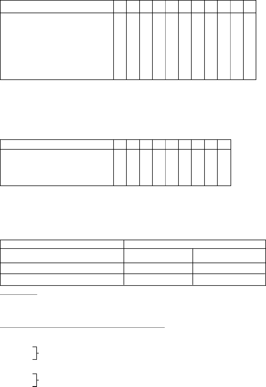
Input connections
Standard amplifiers are fitted with Locking 5 pin DIN input connectors on a 180 degree spacing pattern. See Fig. 2 below to
identify the pin numbers. The input connections will vary depending upon which module is being used in the corresponding
module position, as follows:
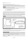
Balanced microphone & line input modules i.e. M24 to M30 and L24 to L32 inc.
Standard Locking 5 pin DIN -
Pin 1
Balanced input
Pin 3
Pin 2 Signal earth (cable audio shield)
Pin 4
Priority control (except audio activated modules)
Pin 5