


MACRO range installation manual. Issue 6
Page 16
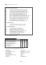
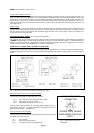
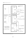
AUXILIARY OUTPUT CONNECTION
A standard 25 way D connector on the amplifier rear provides all the auxiliary connections associated with current sinking,
alarms, auxiliary DC and signal outputs, etc., where applicable. The standard connections are as follows:
1 250mA current sink activated by input module No.1 during priority access
2 250mA current sink activated by input module No.2 during priority access
3 250mA current sink activated by input module No.3 during priority access
4 250mA current sink activated by input module No.4 during priority access
5 250mA current sink activated by input module No.5 during priority access
6 250mA current sink activated by input module No.6 during priority access
7 250mA current sink activated by input module No.7 during priority access
8 250mA current sink activated by input module No.8 during priority access
9 250mA current sink bus activated by any module gaining priority access
10 250 mA CDM current sink bus activated by any module with this feature
11 0Vforgeneral purpose
12 Nominal 24V+ DC unregulated output, for use with current sinks
13 Mains power input failure
alarm contacts - normally open
14
15 DC power input failure
alarm contacts - normally open
16
17
18 process/equaliser control
19 for future use.
20 nc
21 nc
22 nc
23 50V duplication of
24 0 100V loudspeaker
25 50V output terminals
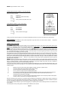
Priority controlled DC current sinks
This unusually comprehensive feature is rarely found on general purpose amplifiers but is useful in microphone paging or alarm
systems where a number of operations may be required co-incident with the use of the priority facilities, e.g.
a) The introduction of page only 100 Volt loudspeaker circuits by using relays to switch them on only during paging.
b) The restoration to full volume of a remote 100 Volt loudspeaker group volume control, such as the Mustang MVC series.
c) The powering of lamps at a microphone position, to indicate that the amplifier priority system is already in use (by an alarm
tone generator for example)
d) The interruption by means of a relay of the sound output of another amplification system.
e) The sending of a low-level paging signal by means of a relay, to another remote amplification system
f) Control of a designated loudspeaker zone control unit from the Mustang ZC or MC ranges.
The principle of operation is that when the signal priority circuit of any of the input modules is activated, the associated DC current
sink is operated and the associated terminal of the Auxiliary output connector - becomes a 0 Volt point. This is used to complete
a simple external circuit comprising relays or lamps etc., connected to the +24V DC terminal.
Terminals 1-8 are individual sinks controlled individually, whilst terminal 9 is activated whenever ANY of the individual sinks is
operated.
The current sinks are polarity protected for use in positive (+ve) applications up to 40V. DO NOT ATTEMPT to pass more than
250mA.
NEVER connect the +24V and current sink connections directly together - serious damage to the module will result. In the off state
there is effectively no connection.
See APPENDIX B for typical applications of the Auxiliary Output connections.
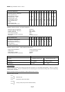
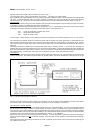
Chime duration monitor sinks - (CDM)
This facility is provided on those modules which feature a chime generator. The sink output lasts for the duration of the chime
tones (which are triggered on priority access) and the the individual sinks are connected to a sink bus
so that a lamp may be energised on a paging microphone to indicate at which point to commence speaking. This connection is
unfused, and is limited to 250mA from a positive (+ve) source. See APPENDIX B for typical application.
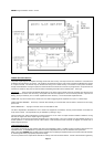
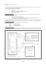
100V line output
This is an extension of the rear 100V loudspeaker output barrier terminals to facilitate all connections to be pluggable if required.
24V DC supply
The 24V+ terminal of the Auxiliary output connector provides an unstabilised DC supply, which is limited to 1 amp by an internal
fuse on the pre-amplifier stabiliser module (see APPENDIX E) and the return is via the 0V terminal. This feature would normally
be used with the DC current sink.
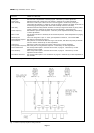
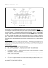
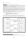
Notes:
a) The current sink connections originate on
individual modules. These current sinks are unfused
and can carry a maximum of 250mA from a positive
(+ve) source.
b) The pin 12 connection originates from the pre-
amplifier stabiliser module (PS.9 etc.) where a F1A
fuse is located - see APPENDIX E
c) The fail alarm connections are open when
the unit is de-energised, and closed during normal
powered operation.