


Page 13
MACRO range installation manual. Issue 6
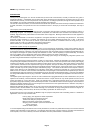
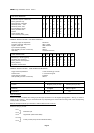
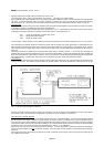
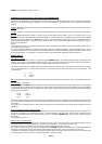
Signal arrangements and DIN cable connections are shown in Fig. 4
As a factory fitted option, a line input transformer may be fitted. See page 21 for further details.
Slave amplifiers have a fixed sensitivity and no input control is provided on standard models. The input impedance is approximately
10k ohms. Immediate technical advice for specific problems is available from the Technical Services Department, Mustang
Communications Ltd. Please also see the section of this manual which covers earthing and earth/hum loops, on page 20.
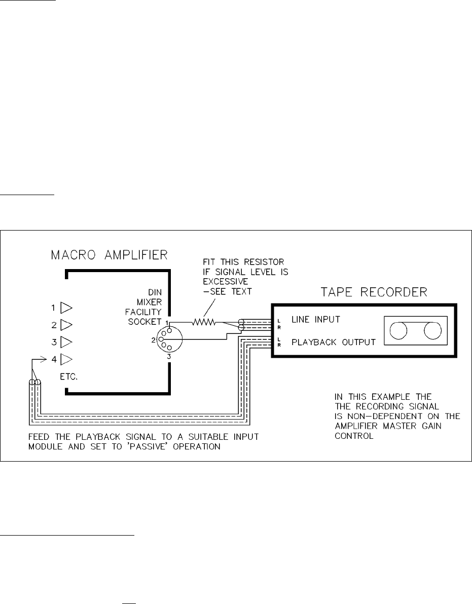
Tape recording
The mixer facility socket of mixers and mixer amplifier units will provide suitable signals for tape recording, though it will normally
be necessary to make up a suitable recording and/or playback lead.
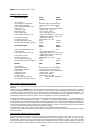
This socket is associated with the master gain control, so either pin 1 or pin 3 of the standard Locking DIN connector may be taken
as the signal connection dependent on whether the recorded signal is to be influenced by it:-
Pin 1 signal non-dependent on master gain control
Pin 2 signal earth (cable braiding)
Pin3 signal via master control
For recording on a stereo recorder connect both left and right channel signal input connections together to pins 1 or 3 as required.
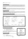
The manufacturers handbook should be consulted to ensure that the recorder will accept signal levels of approximately 0.75V
without distortion and that the recorder does not short out the signal recording connections when in the playback mode. In either
case, insert a resistor of suitably high value in series with the recording lead. An experimental starting value would be 22k ohms.
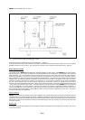
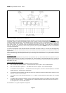
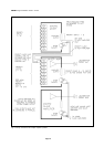
See Fig. 6
Certain tape decks send a signal from the tape playback output during a recording session. If, in this case, the recording and
playback leads are connected simultaneously to an input channel of the amplifier, a closed-loop feedback path to the amplifier will
result and cause problems unless the loop is broken. This in its simplest form would necessitate disconnecting the tape playback
lead whilst recording, or alternatively, reducing to zero the amplifier input gain control associated with playback.
Tape playback
A playback signal would preferably be routed through a standard line input module (L25, L33, L34 etc) which accommodate a wide
variety of signal levels. The module may be located in any module position. The L25 for example has a floating input circuit, and
would be most useful where hum loops are likely to be a problem - such as in complex sound installations. See the module details
for connection data. The module will need to be set to the passive mode of operation - see page 12.
Interconnection of several amplifiers
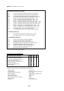
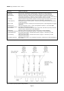
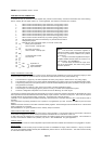
Larger scale amplification systems may necessitate the interconnection of several amplifiers. The most usual situation would be
the attachment of extra slave amplifiers to a mixer amplifier in order to increase the available power output whilst delivering the
same program. This is made possible by linking the appropriate mixer facility socket pin (pre or post master gain where available)
of the mixer amplifier to the input pin of the slave amplifier(s). The cable should be single conductor screened, and the braid/shield
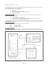
connections should also be made between the appropriate pins. See Fig. 7 for clarification.
NOTE: This is the only means of interconnection that is permitted. It is most inadvisable to attempt to combine the loudspeaker
outputs of several amplifiers into one loudspeaker feed line. At the very least, severe problems, and most likely serious damage
will result.
The loudspeaker system should always be planned such that it is divided up into sections, each of which will be powered by just
one amplifier output section.
Fig. 6 Tape record and playback connections