


Page 17
MACRO range installation manual. Issue 6
COMBINING THE INPUT/OUTPUT FACILITIES OF TWO OR MORE UNITS
This may be considered where one single amplifier cannot provide enough input facilities or output power for a particular application.
Mixers may be combined with mixer amplifiers, and with slave amplifiers in any combination via their respective mixer facility
sockets.
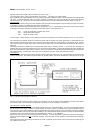
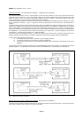
Example M2508 and M250 to provide 8 inputs and 500 Watt output to two loudspeaker zones. Interconnect using pins 3 of each
mixer facility socket.
Example M2508 and two M100 to provide 8 inputs and 450 Watt output. Interconnect using pins 3 of each mixer facility socket.
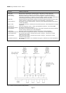
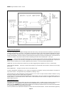
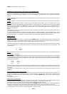
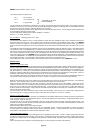
Example M8/M and M1008 to provide 15 priority inputs and 100 Watts output capability. Fit an L.25 module in input 1 of the
M1008 and drive it from the mixer facility output of the M8/M. Connect the ANY sink of the M8/M to pin 5 of the input No.1 M1008
such that any priority operation of the M8/M seeks access to input No.1 M1008 as though a normal input. All individual sinks on
either unit will still be relevant. The mixer facility of M1008 may be used to drive slave amplifiers in the same system if required.
See Fig. 9 for clarification.
NOTE
The loudspeaker system should always be planned such that it is divided up into sections, each of which will be powered by just
one amplifier output section.
It is most inadvisable to attempt to combine the loudspeaker outputs of several amplifiers into one loudspeaker feed line. At the
very least, severe problems, and most likely serious damage will result. Whilst it is technically feasible, the risks faced will render
it an impractical option. For clarification, consult the System design department of Mustang Communications Ltd.
POWER SUPPLY
AC Mains power input
A standard IEC 3 pin mains connector is supplied with each MACRO amplifier. It is essential that the Earth connection is made
properly, as the chassis of the amplifier is earthed via this facility. The mains power required is 230V to 240V AC at 50-60Hz. If
a slightly lower voltage is used, then the battery charging facility (if fitted) may be impaired.
The power requirement for the amplifier, even when used at full power, is minimal and should be taken from the AC mains supply
via a 3 core flexible cable. It is vital that the connections to the mains input line socket are made to the correct terminals. The
connections are:-
L Live
N Neutral
E Earth
DO NOT operate the amplifier under any circumstances without an electrical earth connected. This is a permanent safety earth.
DC power input (if applicable)
Certain models in the MACRO range are designed to operate from 24V DC during periods of mains supply failure. It is permissible
for this voltage to vary between 20V and 28V without undue problem, though the battery charging capability will vary accordingly.
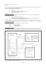
A style MS.62 military style connector is supplied with each amplifier, and the corresponding connections are printed alongside the
panel connector, as follows;
Pin A +24V
Pin B Chassis
Pin C - (0V)
Important: If either positive or negative terminals must unavoidably be earthed, it is preferable that it be NEGATIVE. Note that the
DC connections are not totally free of earth, as the signal earth and DC (-) of the amplification are connected to chassis by a 220
ohm resistor.
Any conflict of DC earthing is likely to result in severe damage to the module printed circuit tracks should incoming circuitry be
earthed too.
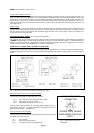
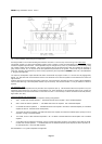
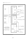
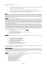
Systems powered by both AC and DC supplies
Systems utilising several MACRO amplifiers to be powered from both AC and emergency DC supplies should be connected such
that the AC is supplied by the routine mains supply - for normal operation, and upon failure of this, the DC is supplied from an
emergency DC battery system with integral charging circuitry. The internal MACRO battery charger circuit should be disabled
(see below).
For clarification see Fig. 10
Main ON-OFF front panel switch
For mains powered MACRO equipment (or non standard DC only units) a two pole switch is used. Mains powered units are
switched in the Neutral and Live connections. DC units are switched in the +ve DC input connection only.
AC Mains/DC equipment utilises a three pole switch which combines both the above functions.
Due to the very high inrush current of an AC mains/DC powered MACRO amplifier, a time lapse circuit and holding solenoid are
employed. The DC section of the power switch therefore carries minimal current. This is not a feature of mixer units.
If a loaded slave amplifier is subject to an input signal during the switch-on sequence using only the DC input, the resulting drain
on the time lapse circuit may prevent the holding solenoid from operating properly.