


ASSEMBLY
8
F-051302L
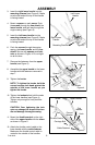
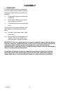
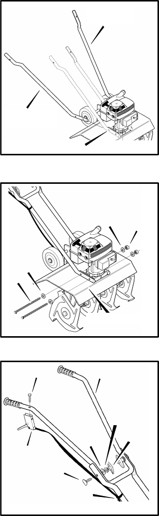
3. Insert the right lower handle into the
mounting channel (see Figure 3). Make
sure the flat end at the top of the handle
is facing inward.
4. Mount a spacer on each screw. Push
the screws through the tine shield, the
lower handle, and half way through the
engine casing (see Figure 4).
5. Insert the left lower handle into the
mounting channel (see Figure 3). Make
sure the flat end at the top of the handle
is facing inward.
6. Push the screws through the engine
casing, the lower handle, and the tine
shield. Secure with spacers and lock-
nuts as shown in Figure 4. Do not tight-
en at this time.
7. Remove the fasteners from the upper
handle (see Figure 5).
8. Assemble the upper handle to the lower
handles with the fasteners removed in
step 7.
9. Tighten the knobs.
NOTE: To tighten the knobs, hold the
curved carriage bolt head against the
outside of the lower handle as you
tighten the knobs.
10. Tighten the locknuts that hold the ends
of the lower handles (see Figure 4).
Tighten only enough to firmly hold the
handles.
CAUTION: Over tightening the lock-
nuts can change the shape of the han-
dle and damage the engine casing.
11. Mount the throttle control on the right
side of the upper handle with the screw
as shown in Figure 5.
12. Attach the throttle control cable to the
lower handle with the cable fastener.
Make sure the throttle control cable is
routed to the outside of the handles.
Figure 3
Left Lower
Handle
Right Lower
Handle
Mounting Channel
Screw
Spacer
Spacer
Locknut
Tine Shield
Figure 4
Figure 5
Screw
Throttle Control
Carriage Bolt
Flat
Washer
Curved
Washer
Knob
Upper Handle
Cable Fastener