


INDUSTRIAL GENERATOR SETS — APPLICATION & INSTALLATION MANUAL — REV. #4 (09/07/07) — PAGE 69
ELECTRICAL INSTALLATION — DC CONTROL WIRING
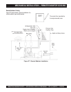
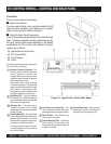
Control Wiring
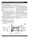
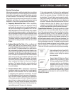
The genset control box is located either on top or on the
side of the alternator housing (see Figure 30 below). It
contains connection points for remote control and monitor
options which are located on the terminal block within the
electronics box.
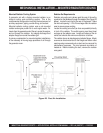
Remote Control / Monitor Connections
Customer remote control / monitor connections are attached
to the terminal block. Optional equipment such as a remote
annunciator panel, sensing devices used to monitor genset
operation, remote start/stop switches, etc. are attached to
this terminal block. Driver signals for customer supplied
relays are also provided for several alarm and shutdown
conditions.
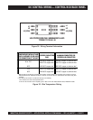
Terminal Block Wiring
Due to the wide variety of devices that can be attached to
the relay outputs of terminal blocks, the electrical contractor
must determine the gauge of
stranded copper
wire that is to
be used at the relay connections.
Switched B+
Switched B+ is fused. See relay connection description.
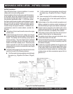
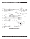
Digital Connections
Digital connections to the genset controller should be
terminated directly to the controller with the following
requirements:
Figure 30. Control Box Location
z
18 gauge twisted pair cable with an overall shield
z
Overall cable should include the number of twisted pairs
as indicated on the customer connection diagram
z
Network cable SHOULD NOT be run in the same conduit
as the AC power output conductors
z
Length should be 1000 feet maximum
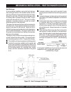
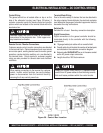
Stranded copper wire must be used for all customer
connections to the electronics box. Solid copper wire
may break due to vibration.
Always run control circuit wiring in a separate metal
conduit from AC power cables to avoid inducing currents
that could cause problems within the control circuits.
When making connections to the terminal for customer
control / monitor control functions, be sure the battery
power is disconnected from the terminal block by
removing the 5 amp control power fuse.