


PAGE 36 — INDUSTRIAL GENERATOR SETS — APPLICATION & INSTALLATION MANUAL — REV. #4 (09/07/07)
MOUNTING — VIBRATION ISOLATORS
Vibration Isolators
Installation and Adjustment Procedure
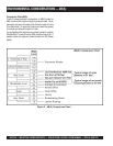
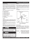
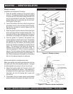
1. Place the vibration isolators on the genset support
structure. The isolators should be shimmed or grouted
to ensure that all of the isolator bases are within 0.25
inch (6 mm) elevation of each other. The surface the
isolator bases rest on must also be flat and level.
(See Figure 9 to the right.)
2. Loosen the snubber lock nuts so that the top plate of
the isolator is free to move vertically and horizontally.
Be sure the top plate is correctly aligned with the
base and springs.
3. Place the genset onto the isolators while aligning the
skid's mounting with the threaded isolator hole. The
top plates will move down and approach the base of
the isolator as the weight of the generator is applied.
4. Once the genset is in position, the isolators may
require adjusting so that the set is level. The isolators
are adjusted by inserting the leveling bolt through
the skid and into the isolator (the leveling bolt's
locking nut should be threaded up towards the bolt
head). The leveling bolt will adjust the clearance
between the top plate and the isolator base. A
nominal clearance of 0.25 inch (6 mm) or greater is
desired. This will provide sufficient clearance for the
rocking that occurs during start-up and shutdown. If
the 0.25 inch clearance is not present, turn the leveling
bolt until the desired clearance is achieved.
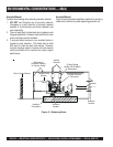
Set mounted radiator-cooled generator sets:
Make sure radiator skid and engine/alternator skid are
level with each other after adjusting isolators. Improper
fan belt alignment may occur is the unit is not level.
5. Adjust the leveling bolts until the set is level and
sufficient clearance still remains. The clearance on
all isolators should be roughly equal. Once all isolators
have been set, lock the leveling bolt in place with
the lock nut.
6. The snubber nuts must remain loose to provide better
isolation between the genset and support structure.
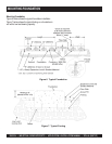
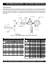
Figure 9. Vibration Isolator
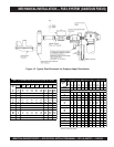
Figure 10. Vibration Isolator Installation