


PAGE 76 — INDUSTRIAL GENERATOR SETS — APPLICATION & INSTALLATION MANUAL — REV. #4 (09/07/07)
AC WIRING
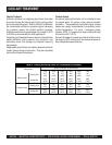
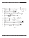
Generator Voltage Connections
The generator output voltage and maximum current rating
are specified on the generator set nameplate. Line-to-neutral
voltage is always the lower voltage shown and the line-to-
line voltage is the higher rating.
The generators are available at the voltages shown in the
wiring diagram of the genset. The genset is connected at
the factory to produce a specified voltage per customer order.
Before shipping, the factory tests the generator set at the
specified voltage.
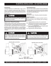
Load Connections (Connecting the Load)
All loads are connected to the generator by bolting the
stranded
load wires to the appropriate terminals on the
generator output circuit breaker. The terminals are marked
for identification to indicate the line and neutral connections.
Load Balancing
When connecting loads to the generator set, balance the
loads so the current flow from each line terminal is about
the same. This is especially important if both single phase
and three phase loads are connected.
Unbalanced loading
of a genset causes unbalanced phase voltages.
Any combination of 1Ø and 3Ø loading can be used as long
as each line current is about the same, within 10% of the
median value and no line current exceeds the nameplate
rating of the generator. Check the current flow from each
line after connections by observing the control panel
ammeter.
Grounding
The following is a brief description of system and equipment
grounding of permanently installed AC generators within a
facility wiring system. It is important to follow the
requirements of the local and county electrical codes.
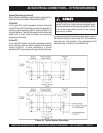
System Grounding
System grounding is the intentional grounding of the neutral
point of a wye-connected generator, the corner of a delta-
connected generator, or the neutral point of one phase winding
of a delta-connected generator, depending on the system
voltage required in the application. It is common to ground
the neutral point of a wye-connected generator and bring out
the neutral (grounded circuit conductor) in a 3Ø four-wire
system.
A corner-grounded delta system has a grounded circuit
conductor that is not a neutral and a "wild leg" that must be
identified by orange color coding and connected to the middle
pole of the 3Ø equipment.
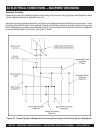
System Grounding Methods
Solid Grounding
This method is typically used and required by the National
Electrical Code (NEC) on all low voltage systems (600 volts
and below) with a grounded circuit conductor (most often a
neutral).
The system is grounded with a direct connection by a
conductor (the grounding electrode conductor) with no
intentional impedance to earth (grounding electrode).
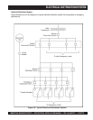
Ungrounded
Ungrounded systems are special applications where no
intention of connection is made between the AC generator
system and earth. These systems are occasionally used
on 3Ø three-wire systems (no grounded circuit conductor)
operating at 600 volts or below, where continuity of power
with one ground fault is required or desirable, and qualified
service electricians are on site. An example would be a
critical process industry.
Correct grounding in standby
systems that are solidly
grounded is a function of the
transfer switch equipment used
(solid neutral or switched neutral).
NOTE
AC ELECTRICAL CONNECTIONS — SYSTEM GROUNDING