


INDUSTRIAL GENERATOR SETS — APPLICATION & INSTALLATION MANUAL — REV. #4 (09/07/07) — PAGE 33
Mounting
Mounting the generator set is a critical part of the installation.
A proper foundation must be able to support the weight of
the generator set and its accessories, resist dynamic loads,
and not transmit excessive noise and vibration. Foundations
can be located on the floor, roof, indoors, or outdoors.
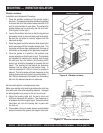
Generator sets are typically mounted on a steel skid that
provides support. Vibration isolators are recommended
between the skid and the foundation to provide stable
operation and avoid installation damage. Bolting the
generator set directly to the floor or foundation can result in
excessive noise and vibration, and possible damage to the
genset and floor/foundation. See Vibration Isolators on page
36 for details.
Access to Set
Whenever choosing a generator site location, always allow
room for service personnel and operators to gain the proper
access to the unit. Always provide adequate lighting around
the unit.
Mounting on a Slab Floor
When mounting the genset on a concrete slab floor, a
concrete pad should be poured on top of the floor. The
concrete pad should be reinforced concrete with a 28 day
compressive strength of at least 2500 psi (173 kPa), however
3000 psi is recommended. It should be at least 6 inches
(150 mm) deep and extend at least 6 inches (150 mmm)
beyond the generator skid on all sides. Type J or L bolts
may be used to anchor the skid or vibration isolators to the
pad. Where allowed, drill-in anchors can be used.
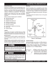
Mounting on a Sub-Base Fuel Tank
When mounting the genset on a subbase fuel cell, the
vibration isolators may be installed between the genset and
the fuel tank. The fuel tank must be able to support the
weight of the genset and resist the dynamic loads. It is
recommended that the tank be mounted with air space
between the bottom of the tank and the floor underneath to
reduce corrosion and permit visual inspections for leaks.
Another method is to size the isolator to support the weight
of the engine-generator accessories, subbase fuel cell, and
fuel. Isolators should be mounted underneath the tank.
MOUNTING FOUNDATION
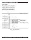
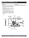
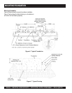
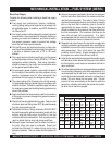
Mounting on a Vibration Isolating Foundation
When mounting the genset on a foundation to reduce the
transmission of vibrations to the building, the weight (W) of
the foundation should be at least 2 times the weight of the
genset itself to resist dynamic loading. Figure 6 on page 34
illustrates a typical vibration isolating foundation.
Consider the following when mounting on a vibration isolating
foundation:
The foundation should extend at least 6 inches beyond
the skid on all sides. This determines the length (L) and
width (w) of the foundation.
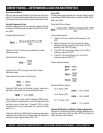
Calculate the height (h) of the foundation necessary to
obtain the required weight (W) by using the following
formula:
where d is the density of concrete, typically 145 lbs/ ft
3
(2322 kg/ m
3
)
For convenience in general servicing such as radiator,
fan belt, and oil filter maintenance, the surface of the
mounting base should be at least 6 inches (152 mm)
above the floor.
The foundation must extend below the frost line to
prevent heaving.
The foundation should be reinforced concrete with a 28
day compressive strength of at least 2500 psi (173 kPa),
however 3000 psi is recommended.
The total weight (TW) of the genset, fuel, and
foundation usually results in a soil bearing load (SBL) of
less than 2000 lbs / ft
2
(96 kPa). Although this is within
the load bearing capacity of most soils, always find out
the allowable soil bearing load by checking the local
code and the soil analysis report of the building. The
soil bearing load can be calculated by using the
following formula:
where "L" and "w" are the length and width of the foundation.
z
Type J or L bolts should be used to anchor the skid or
vibration isolators to the foundation.