


PAGE 66 — INDUSTRIAL GENERATOR SETS — APPLICATION & INSTALLATION MANUAL — REV. #4 (09/07/07)
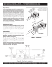
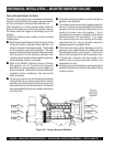
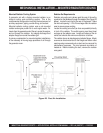
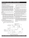
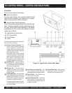
Figure 28. Hot Well Installation
Hot Well Installation
Figure 28 below shows a typical installation of a remote
radiator with a hot well cooling system.
A remote radiator with a hot well can be used if the elevation
of the radiator above the crankshaft center line exceeds
the allowable coolant static head on the genset. Refer to
the generator specification sheet. In a hot well system,
the engine coolant pump circulates coolant between engine
and hot well and an auxiliary pump circulates coolant
between hot well and radiator. A hot well system requires
a careful design and proper installation. In addition to the
considerations under the remote radiator, consider the
following:
MECHANICAL INSTALLATION — HOT WELL COOLING
z
1/4 of the coolant volume pumped per minute through
the radiator (e.g., 25 gallons if the flow is 100 gpm),
plus
z
Volume required to fill the radiator and piping, plus
z
Five percent (5%) of the total system volume for
thermal expansion
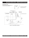
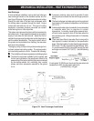
Careful design of the inlet and outlet connections and
baffles is required to minimize coolant turbulence and
maximize blending of engine and radiator coolant flows.
Coolant must be pumped to the bottom tank of the
radiator and returned from the top tank, otherwise the
pump will not be able to completely fill the radiator.
The auxiliary pump must be lower than the low level of
coolant in the hot well so it is always primed.
The radiator should have a vacuum relief check valve
to allow drain down to the hot well.
The hot well should have a high volume breather cap to
allow the coolant level to fall as the auxiliary pump fills
the radiator and piping.
To obtain the
net power
available from the genset, add
the fan load indicated on the genset specification sheet
to the power rating of the set and subtract the power
consumed by the remote radiator fan, ventilating fans,
coolant pumps, and other accessories required for the
genset to run.
The bottom of the hot well should be above the engine
coolant outlet.
Coolant flow through the hot well / radiator circuit should
be approximately the same as coolant flow through the
engine. The radiator and the auxiliary pump must be
sized accordingly. The pump head must be sufficient
enough to overcome the sum of the static and friction
heads in the hot well / radiator circuit.
One foot of pump
head is equivalent to 0.43 PSI of coolant friction head
(pressure loss) or one foot of coolant static head (height
of liquid column).
The liquid holding capacity of the hot well should not be
less than the sum of the following volumes:
z
1/4 of the coolant volume pumped per minute through
the engine (e.g., 25 gallons if the flow is 100 gpm),
plus