HDA-SERIES WALK-BEHIND TROWEL — OPERATION AND PARTS MANUAL — REV. #9 (07/02/10) — PAGE 15
GENERAL INFORMATION
HDA-SERIES Walk-Behind Trowel Familiarization
This walk-behind trowel is designed for the
floating
and
finishing
of concrete slabs.
Take a walk around the trowel. Take notice of all the major
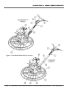
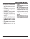
components (see pages 16 and 17) like the engine, blades,
quick pitch control, air cleaner, centrifugal stop switch etc. Check
that there is always oil in the engine.
Read
all the safety instructions carefully. Safety instructions will
be found throughout this manual and on the trowel. Keep all
safety information in good, readable condition. Operators should
be well trained on the operation and maintenance of the trowel.
Before using your trowel, test it on a flat watered down section of
finished concrete that is free of any debris and other objects.
This trial test run will increase your confidence in using the trowel
and at the same time it will familiarize you with the trowel’s
controls. In addition you will understand how the trowel handles
under actual conditions.
Engines
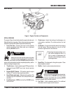
This trowel is available with an 11 HP or 13 HP gasoline engine.
Refer to the engine owner’s manual for instructions regarding
the operation and maintenance of your engine. Please contact
your nearest Multiquip Dealer for a replacement should the
original manual disappear or otherwise become unusable.
Drive System
Power is transferred from the engine to the gearbox input shaft
via a V-belt or pulley drive system. The pulley engages using a
centrifugal clutch.
Gearbox
The
gearbox
is located beneath the engine and transfers power
to the
rotor
or
spider
assembly. The gearbox controls the
rotational speed of the trowel and is equipped with two shafts
(input and output).
Spider
The vertical output shaft of the gearbox connects to a cast hub
called the
spider
. The spider has 4 arms that extend outward
that are used for attachment of blades or other accessories.
Remember as the gearbox output shaft rotates so does the spider
assembly.
Blades
The blades of the trowel finish the concrete as they are rotated
around the surface. Blades are classified as
combination
(8
inches wide),
float
(10 or 8 inches wide), and finish (6 inches
wide). This trowel comes equipped with either
three
or four
blades per rotor equally spaced in a radial pattern and
attached to vertical rotating shaft by means of a
spider
assembly.
Centrifugal Stop Switch
In the event of a trowel runaway condition (operator releases
the handle), a
centrifugal stop switch
or
manual clutch
depending on which trowel you have, will stop the engine
and bring the trowel to a halt.
GENERAL INFORMATION
Moving the HDA-SERIES Walk-Behind Trowel
This walk-behind trowel is designed to be moved and handled
in several ways. The easiest way to lift the trowel is to use the
auxiliary lifting tube
that is attached to the main handle. See
page 24, Figure 20. When using the auxiliary tube, always use
two persons
to lift the trowel.
Some models have a
lifting bail
(option) installed. A strap or
chain can be attached to the lifting bail, allowing a forklift or
crane to lift the trowel up onto a slab of concrete. Use a lifting
device of adequate lifting capacity to lift the trowel.
Training
For proper training, please use the “TRAINING CHECKLIST”
located in the front of this manual (Page 6). This checklist will
provide an outline for an experienced operator to provide training
to a new operator.
NEVER attempt to
lift
the trowel by yourself.
ALWAYS get the assistance of another
person to help lift the trowel or use a crane or
lifting device to move the trowel.
CAUTIONCAUTION
CAUTIONCAUTION
CAUTION


