


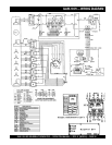

GAW-135H DC WELDER/AC GENERATOR — OPERATION MANUAL — REV. #1 (06/23/04) — PAGE 27
GAW-135H — WELDER OPERATION
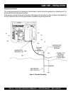
Connecting the Welding Cables
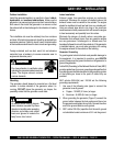
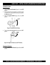
1. Make sure the generator/welder is OFF (not running).
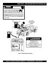
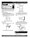
2. Attach the correct size terminal connector to the free
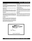
end of each cable. NEVER connect
bare or exposed
wires (Figure 23) directly to the terminals. Exposed wiring
may cause electrical arcing or dilectric breakdown from
poor connection.
3. When connecting the cables NEVER allow the cable or
welder output terminals to touch each other.
4. The welder's output terminals are marked positive (+)
and negative (-). Connect the welding cables to the
output terminals as referenced in Table 5.
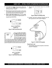
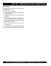
2. Attach the correct size terminal connector (Figure 24)
to the free end of each cable.
NOTE
When selecting a welding cable, the
welding cable should be larger in
size as it becomes longer or its
current becomes higher. Use Table 6
as a guideline when selecting a
suitable welding cable. The calculated values listed in Table 6
are based on a maximum voltage drop of 4 volts.
Figure 23. Welding Cable (Bare Wires)
Figure 24. Welding Cable (Terminal Connector)
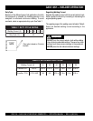
seitiraloPdnaselbaCgnidleW.5elbaT
ytiraloPdohteMgnidleWnoitacilppAlacipyT
thgiartS
ytiraloP
gnidnuorG)+(evi
tisoP
)lateMesaB(
redloHgnidleW)-(evitageN
lairetamleetsrofgnidlewcrA
rofdna,serutcurtslarenegfo
.setalpkciht
yollareppocrofgnidlewcrA
esreveR
ytiraloP
redloHgnidleW)+(evitisoP
gnidnuorG)-(evitageN
)lateMesaB(
gnid
leWpu-dliuB
gniguogriA
setalpnihtfognidlewcrA
leetssselniatsfognidlewcrA
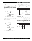
TRAHCGNITCELESELBACGNIDLEW.6ELBAT
gnidleW
tnerruC
:gnideecxEtoNtiucriCdleWnihtgneL)reppoC(elbaClatoT
.tf05
)m51(
tf001
)m03(
.tf051
)m64(
.tf002
)m16(
.tf052
)m16(
.tf003
)m19(
A055#5#5#5#5#4#
A0015#5#4#3#2#1#
A5315#4#2#1#0/1#0/1#