


GAW-135H DC WELDER/AC GENERATOR — OPERATION MANUAL — REV. #1 (06/23/04) — PAGE 19
GAW-135H — CONTROLS AND INDICATORS
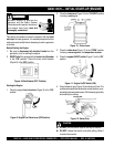
This
HONDA
engine is equipped
with a low oil shutdown capability. A
built in sensor will automatically turn
off the engine should the oil level fall
below a safe operating condition.
Make sure the generator is placed
on level ground. Placing the generator/welder on level ground
will ensure that the low oil sensor will function properly.
NOTE
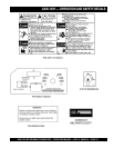
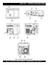
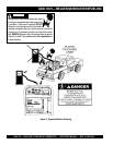
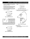
1. Engine ON/OFF Switch – Place this switch in the "ON"
position to start the engine. To turn-off the engine place this
switch in the "OFF" position.
2. Current Selector Knob – Place this knob in the desired
setting when welding is required. There are 6 selectable
settings that range from 40 amps to 135 amps.
3. Connect the welder electrodes to these terminals. Please
note the polarity of the electrodes when connecting them
to the welder.
4. Main Circuit Breaker – This 2-pole 15 amp breaker
protects the generator from short circuiting or overloading.
When starting the generator
always
have the circuit breaker
placed in the "OFF" position.
5. Idle Control Switch – This unit is provided with an
automatic idle control for noise suppression and reduced
fuel consumption. The automatic idle control automatically
engages under a no-load condition. With the automatic
idle control switched “ON”, the engine revolutions will
automatically drop to about 2600 rpm (low-speed
operation) within 3 seconds after the load stops. When the
operation is resumed, the engine speed is automatically
increased to about 3600 rpm (high-speed operation) as
soon as the load is connected.
6. GFCI Receptacle – This receptacle will provide 120V at
all times.
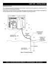
7. Ground – This ground connection point should be
connect to a good earth ground (ground rod).
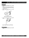
8. Engine Oil Filler Cap – Remove this cap/dipstick when
the adding of engine oil is required. See Table 4 for
recommended type engine oil.
9. Engine Oil Drain Plug – Remove this drain plug when
draining of the oil from the engine crankcase is required.
Fill with recommeded type oil as listed in Table 4.
10. Recoil Starter (pull rope) – Manual-starting method. Pull
the starter grip until resistance is felt, then pull briskly and
smoothly.
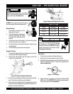
11. Fuel Cock Lever – Turn this lever
downward
to
start
(down)the flow of fuel to the carburetor. Turn
upward
to
stop (
up
)
the flow of fuel.
12. Air Cleaner – Prevents dirt and other debris from entering
the fuel system. Remove wing-nut on top of air filter
cannister to gain access to filter element. NEVER run the
engine without an air cleaner.
13. Choke Lever – Used for starting the engine.
Close
the
choke lever when starting a cold engine or in cold weather
conditions. The choke enriches the fuel mixture.
Open
the
choke lever if starting a warm engine or in warm weather
conditions.
14. Fuel Tank Cap – Remove this cap to add unleaded
gasoline to the fuel tank.
Replenish
with
clean unleaded
gasoline. Make sure cap is tightened securely. DO NOT
over fill. Fuel tank capacity is 1.85 gallons (7 liters).
15. Fuel Gauge – Read this gauge to determine when fuel is
low
.
16. Spark Plug – Provides spark to the ignition system. Set
spark plug gap to 0.6 - 0.7 mm (0.024 - 0.028 inch). Clean
spark plug once a week.
17. Muffler/Heat Shield – Used to reduce noise and emissions.
NEVER touch this
heat shield
when the generator/welder
is in use. Always allow time for the generator to cool down
before performing maintenance.