


DCA-70SSJU SERIES — OPERATION AND PARTS MANUAL (STD)— REV. #5 (06/03/03) — PAGE 29
1
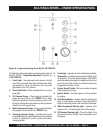
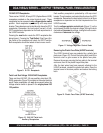
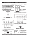
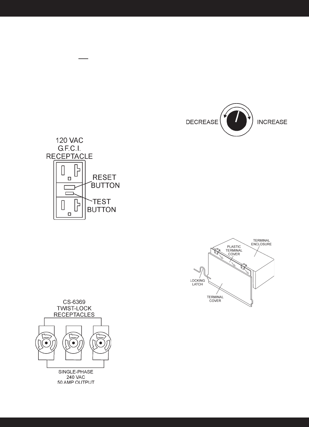
120 VAC GFCI Receptacles
There are two 120 VAC, 20 amp GFCI (Duplex Nema 5-20R)
recepacles provided on the output terminal panel. These
receptacles can be accessed in any
voltage selector switch
position. Each receptacle is protected by a 20 amp circuit
breaker. These breakers are located directly above the GFCI
receptacles. Remember the load output (current) of both
GFCI receptacles is dependent on the load requirements of
the UVWO terminals.
Pressing the
reset
button resets the GFCI receptacle after
being tripped. Pressing the "
Test Button
" (See Figure 9) in
the center of the receptacle will check the GFCI function.
Both receptacles should be tested at least once a month.
Figure 9. G.F.C.I. Receptacle
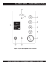
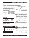
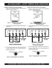
Each auxilliary receptacle is protected by a 50 amp circuit
breaker. These breakers are located directly above the GFCI
receptacles. Remember the load output (current) on all three
receptacles is dependent on the load requirements of the
UVWO terminals.
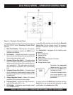
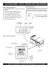
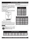
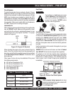
Turn the
voltage regulator control knob
(Figure 11) on the
control panel to obtain the desired voltage. Turning the knob
clockwise will
increase
the voltage, turning the knob counter-
clockwise will
decrease
the voltage.
Figure 10. 240 VAC Twist-Lock
Auxiliary Receptacles
DCA-70SSJU SERIES — OUTPUT TERMINAL PANEL FAMILIARIZATION
Twist Lock Dual Voltage 120/240 VAC Receptacles
There are three 240 VAC, 50 amp auxilliary twist-lock (CS-
6369) recepacles (Figure 10) provided on the output terminal
panel.These receptacles can
only
be accessed when the
voltage selector switch is placed in the
single-phase 240/
120 position.
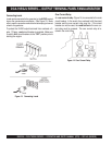
Removing the Plastic Face Plate (UVWO Terminals)
The UVWO terminal lugs are protected by a plastic face
plate cover (Figure 12). Un-lock the locking latch, and lift the
terminal cover to gain access to the plastic face plate.
Remove the screws securing the face plate to the terminal
enclosure, then lift the plastic hinged face plate.
After the load wires have been securely attached to the
UVWO terminals, reinstall the plastic face plate. Place the
terminal cover in the down position and secure the locking
latch.
Figure 11. Voltage Regulator Control Knob
Figure 12. Plastic Face Plate (UVWO Terminals)